70
Parameter List
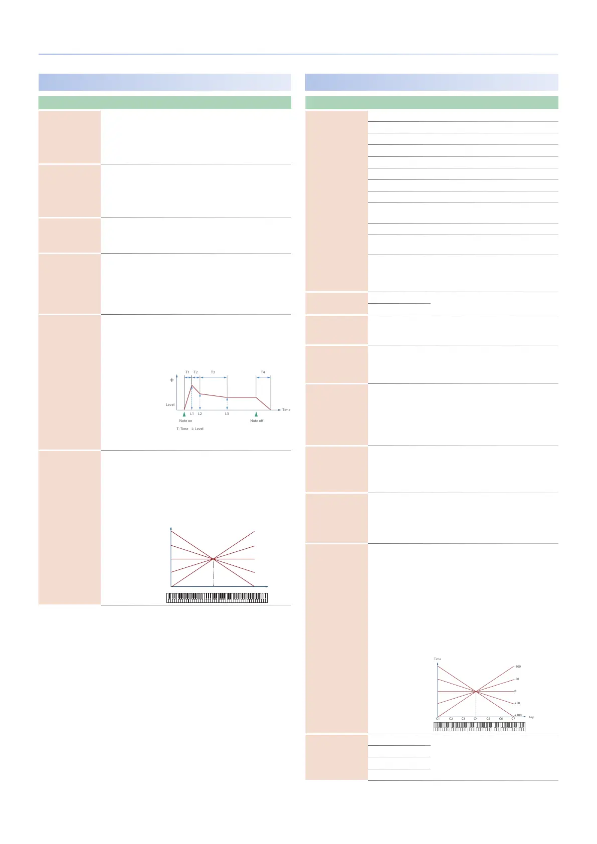
AMP ENV
Parameter Value Explanation
T1 Velocity Sens -100–+100
Specify this if you want keyboard dynamics to
aect the AMP envelope’s Time 1. If you want
Time 1 to be speeded up for strongly played
notes, set this parameter to a positive (+)
value. If you want it to be slowed down, set
this to a negative (-) value.
T4 Velocity Sens -100–+100
Specify this if you want key release velocity to
aect the AMP envelope’s Time 4. If you want
Time 4 to be speeded up for quickly released
notes, set this parameter to a positive (+)
value. If you want it to be slowed down, set
this to a negative (-) value.
AENV LFO Trigger
Switch
OFF, ON
If this is ON, the amp envelope is cyclically
retriggered by LFO1.
* This is eective when Envelope Mode is
SUSTAIN.
T1/Attack,
T2,
T3/Decay,
T4/Release
0–1023
Specify the AMP envelope times (Time 1–
Time 4). Higher settings lengthen the time
until the next volume level is reached. (For
example, Time 2 is the time over which Level
1 will change to Level 2.)
* If ADSR Envelope Switch is ON, the Time 2 has
no eect.
L1,
L2,
L3/Sustain
0–1023
Specify the AMP envelope levels (Level 1–
Level 3).
These specify the amount of change at
each point relative to the reference volume
(the partial level value specied in the Amp
screen).
* If ADSR Envelope Switch is ON, only Level 3
(Sustain) has an eect.
Time Keyfollow -100–+100
Specify this if you want keyboard position
to aect the AMP envelope’s times (Time 2–
Time 4). Relative to the AMP envelope times
at the C4 key (middle C), positive (+) values
cause the times to shorten as you play higher
on the keyboard, and negative (-) values
cause the times to lengthen. Higher values
will produce greater change.
Key
-50
-100
+50
+100
C4C3C2C1 C5 C6 C7
0
LFO1 / LFO2
Parameter Value Explanation
Waveform
(LFO1, LFO2)
Selects the waveform of the LFO.
SIN Sine wave
TRI Triangle wave
SAW-UP Sawtooth wave
SAW-DW Sawtooth wave (negative polarity)
SQR Square wave
RND Random wave
TRP Trapezoidal wave
S&H
Sample & Hold wave (one time per cycle, LFO
value is changed)
CHS Chaos wave
VSIN
Modied sine wave. The amplitude of a sine
wave is randomly varied once each cycle.
STEP
A waveform generated by the data specied
by LFO Step 1–16. This produces stepped
change with a xed pattern similar to a step
modulator.
Tempo Sync Sw
(LFO1, LFO2)
OFF
Set this ON if you want the LFO rate to
synchronize with the tempo.
ON
Rate Note
(LFO1, LFO2)
1/64T–4
This is eective if Rate Sync is ON.
Species the LFO rate in terms of a note
value.
Rate
(LFO1, LFO2)
0–1023
This is eective if Rate Sync is OFF.
Species the LFO rate without regard to the
tempo. Higher values produce a faster LFO
rate (a shorter cycle).
Oset (LFO1, LFO2) -100–+100
Raises or lowers the LFO waveform relative to
the central value (pitch or cuto frequency).
Positive (+) value will move the waveform so
that modulation will occur from the central
value upward. Negative (-) value will move
the waveform so that modulation will occur
from the central value downward.
Rate Detune
(LFO1, LFO2)
0–127
Subtly changes the LFO cycle speed (Rate
parameter) each time you press a key. Higher
values produce greater change.
This parameter is invalid when Rate is set to
“note.”
Delay Time
(LFO1, LFO2)
0–1023
Species the time elapsed before the LFO
eect is applied (the eect continues) after
the key is pressed (or released).
* After referring to “How to Apply the LFO” (p.
72), change the setting until the desired eect
is achieved.
Delay Time Keyfollow
(LFO1, LFO2)
-100–+100
Adjusts the value for the Delay Time
parameter depending on the key position,
relative to the C4 key (center C). To decrease
the time that elapses before the LFO eect
is applied (the eect is continuous) with
each higher key that is pressed in the upper
registers, select a positive (+) value; to
increase the elapsed time, select a negative
(-) value. Higher values will produce greater
change. If you do not want the elapsed time
before the LFO eect is applied (the eect is
continuous) to change according to the key
pressed, set this to “0.”
Fade Mode (LFO1, LFO2)
ON-IN
Species how the LFO will be applied.
* After referring to “How to Apply the LFO” (p.
72), change the setting until the desired eect
is achieved.
ON-OUT
OFF-IN
OFF-OUT

 Loading...