REP
3.1
Control PWB REP
3.2
High
Voltage Power Replacement
Supply
(HVPS)
NOTE:
Step
3E
in
REMOVAL:
Ensure that the
I
Parts List
on
PL
1.2
screws are reinstalled
for
a
proper
I
Parts
list
on
PL
1.2
cloct
ricnl
ground,
Replacement
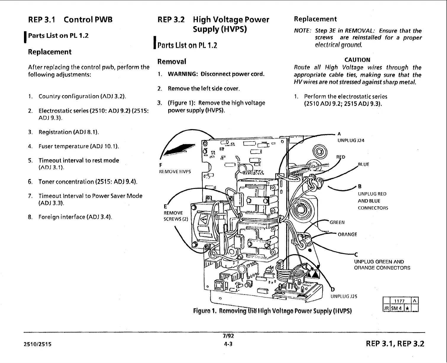
Removal
CAUTION
After replacing the control pwb, perform the
Route
all
High Voltage wires through the
following adjustments:
1.
WARNING:
Disconnect
power
cord.
appropriate cable ties, making sure that the
HV
wires are not stressed against sharp metal.
2.
Remove the left side cover.
Counlry configurnlion
(ADJ
3.2).
1.
Perform the electrostntic series
3.
(Figure
1):
Remove the high voltage
(2510
ADJ
9.2;
251 5ADJ
9,3).
Electrostatic series
(2510:
ADJ
9.2)
(251 5:
power supply
(HVPS).
ADJ
9.3).
Registration
(ADJ
8.1).
Fuser temperature
(ADJ
10.1).
Timeout interval to rest mode
(ADJ
3,l).
Toner concentration
(251
5:
AD1
9.4).
Timeout Interval
to
Power Saver Mode
(ADJ
3.3).
Foreign interface
(ADJ
3.4).
UNPLUG
J24
IU:MOVE
IIVt'S
UNPLUG
RED
AND
BLUE
CONNECTORS
UNPLUG GREEN AND
ORANGECONNECTORS
Flgura
1.
~ornov&Cll~~ l4igli Vol tnga Powor
Supply
(HVPS)
REP
3.1,
REP
3.2
 Loading...