ADJ
9.2
Electrostatic Series
(Old
I
NEW
PHOTORECEPTOR DRUM: Run
25
ft
(7.6
metres) of copies, then allow copier to go into
Type
HVPS)
the power saver mode.
his
adjustment must be performed
in
the
exact order presented here.
PURPOSE
The purpose of this adjustment
is
to obtain
good copy quality by bringing the corotron
and exposure voltages to their required
specification.
1.
Before this procedure check
the following:
s
tight fit exists between the
electrometer probe and the probe
holder. If the fit
is
too loose the
probe will rotate in the holder
during
the
procedure, and cause
on
inaccurate adjustment.
Do
not
cot~lltruu llru ndjusltrrc~~l urrlll
llrls
condition
is
corrected.
the battery of the DMM
is
not at the
end of
its
useful life. Two
indications of this problem are a
,
"B"
on the DMM display or a faded
display when
the
DMM
is
energized.
the
2
VDC scale
is
selected on the
DMM.
the low battery LED
is
not
illuminated on the electrometer.
the charge corotron
is
seated
correctly.
clean the lens, platen, lamp and
corotrons
USED
PlIOTOIIBCtPTOII
DRUM:
Ib.itl
om
copy, then allow the copier to go into the
power saver mode.
WARNING
Disconnect the power cord.
3.
Remove:
the document handler
the left side cover
the right side cover
the upper rear cover
the document transport drive belt
4.
Remove developer module
(REP
9.5).
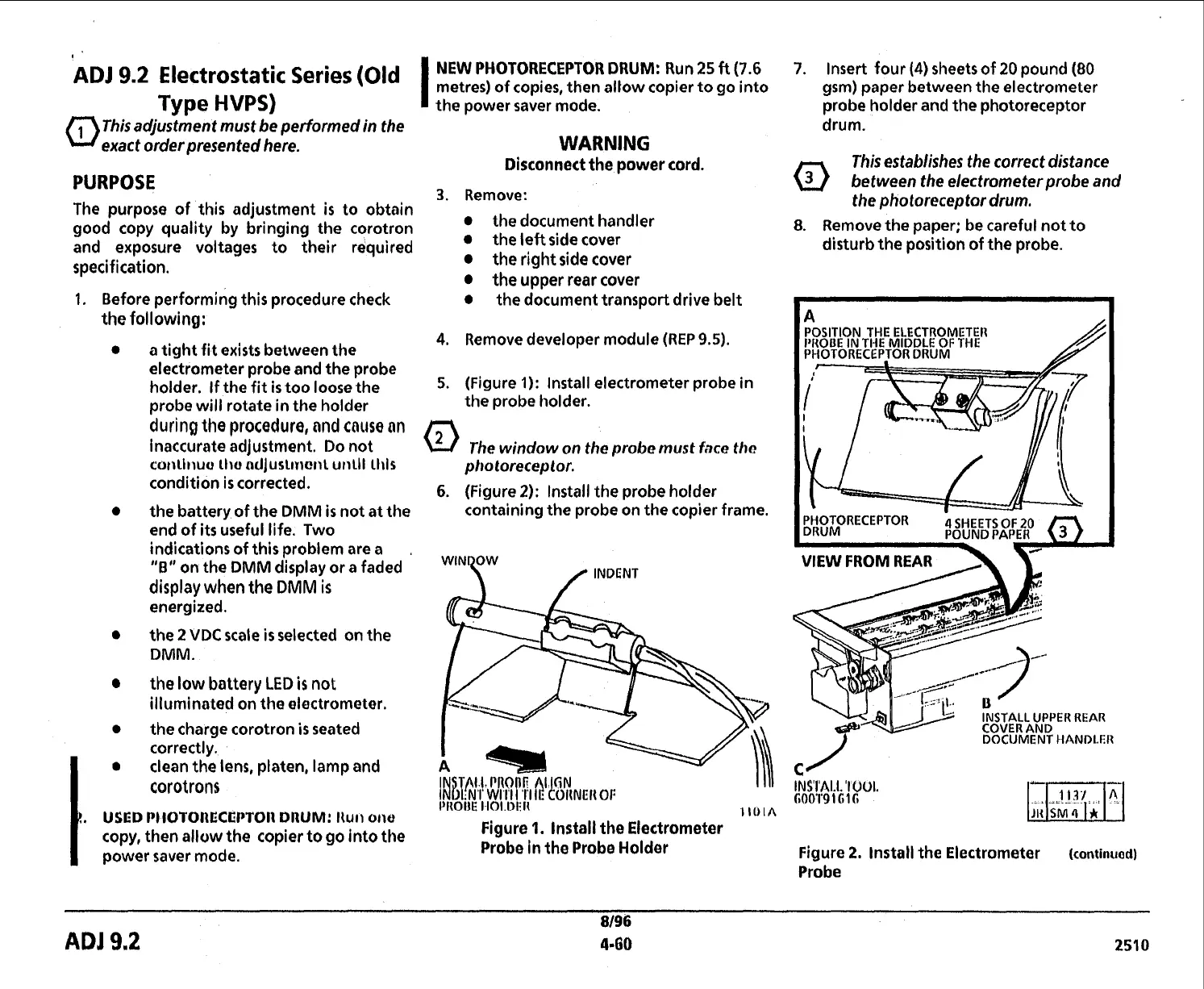
5.
(Figure
1):
Install electrometer probe
in
the probe holder.
The
window
on the
probe
must
face
the
photoreceptor.
6.
(Figure
2):
Install the probe holder
containing the probe on the copier frame.
W'Ny
/
INDENT
Figure
1.
lnstall the Electrometer
Probe in the Probe Holder
7.
Insert four
(4)
sheets of
20
pound
(80
gsm) paper between the electrometer
probe holder and the photoreceptor
drum.
This establishes the correct distance
between the electrometer probe and
the photoreceptor drum.
8.
Remove the DaDer; be careful not to
..
-
disturb the position of the probe.
INSTALL UPPER REAR
COVER AND
DOCUMENT HANDLER
Figure
2.
lnstall the Electrometer
(continuod)
Probe
8/96
ADJ
9.2
4.60
251
o
 Loading...