ADJ
9.3
Electrostatic Series
2510/2515
(New
HVPS)
NOTE:
This adjustment must be performed
in
the exact order presented here.
PURPOSE
The purpose of this adjustment
is
to obtain
good copy quality by bringing the corotron
and exposure voltages to their required
specification.
1.
Before performing this procedure check
the following:
n
light
fit
oxi~tr hatwoon
tlirr
electrometer probe and the probe
holder. If the
fit
is
too loose the
probe will rotate in the holder
during the procedure, and cause an
inaccurate adjustment. Do not
continue the adjustment until this
condition
is
corrected.
the battery of the DMM
is
not at
the end of
its
useful life. Two
indications of this problem are
a
"B"
on the DMM display or a faded
display when the DMM
is
energized.
the
2
VDC
scale
is
selected on the
DMM.
the low battery
LED
is
not
illuminated on the electrometer.
the
chivgc c~rotron
is
serrted
correctly.
NOTE:
When the electrostatic series
is
completed with
a
new photoreceptor
WINDOW
/
INDENT
drum, the image density will be slightly
lighter than when the electrostatic
series
is
completed with a
photoreceptor drum previously used.
If this condition should occur do not
make any further adjustments at this
time.
Used photoreceptor drum: run one
copy and allow the copier to go into
A
low power mode.
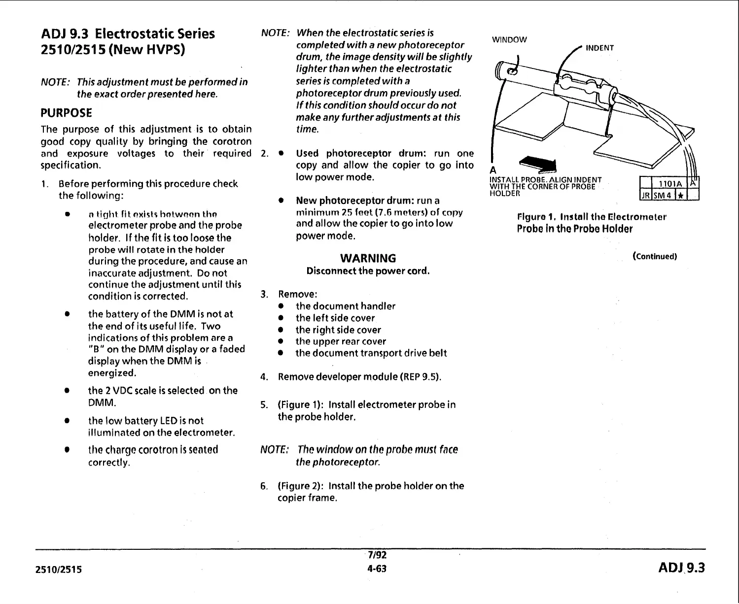
INSTALL
PROBE.
ALIGN INDENT
WITH
THE
CORNER
OF
PROBE
11OlA
HOLDER
New photoreceptor drum: run a
JR
SM4
h
minimum
25
foot
(7,fi
motors)
of
copy
=
Figure
1,
Itistall the Eleclrornaler
and allow the copier to go into low
power mode.
Probo
in
tho Probe Holder
WARNING
Disconnect the power cord.
3.
Remove:
the document handler
the left side cover
the right side cover
the upper rear cover
the document transport drive belt
4.
Remove developer module (REP
9.5).
5.
(Figure
1):
Install electrometer probe in
the probe holder.
(continued)
NOTE:
The
window on
the
probe
must
fnce
the photoreceptor.
6.
(Figure
2):
Install the probe holder on the
copier frame.
 Loading...