I
C
-
Cover lnterlock Open
RAP
(2510
WIOTAG
5)
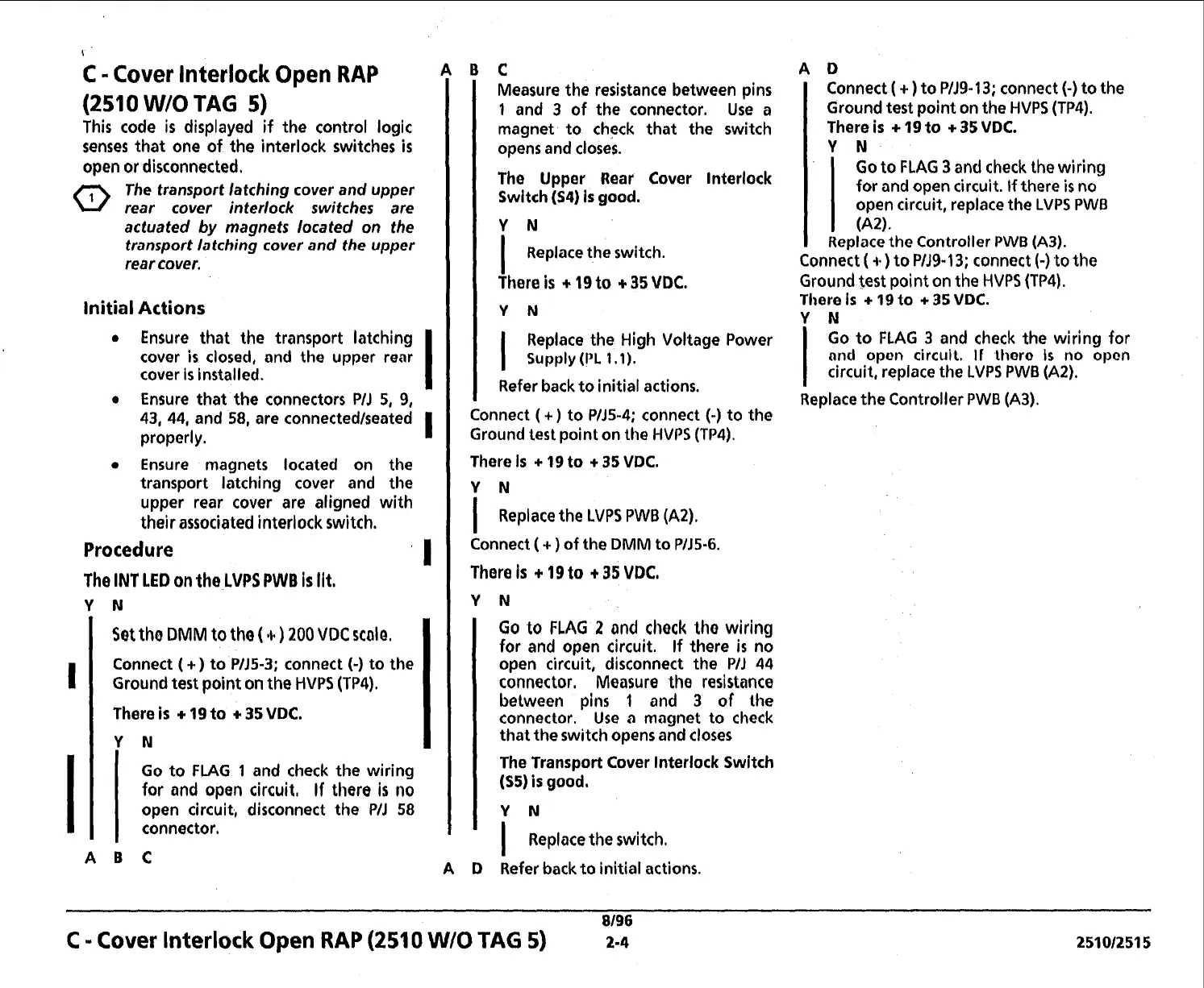
This code
is
displayed
if
the control logic
senses that one of the interlock switches
is
open or disconnected.
The transport latching cover and upper
rear cover interlock switches are
actuated
by
magnets located on the
transport latching cover and the upper
rear cover.
Initial
Actions
Ensure that the transport latching
cover
is
closed, and the upper rear
cover
is
installed.
Ensure that the connectors
PIJ
5,
9,
43, 44, and
58,
are connectedlseated
properly.
I
I
Ensure magnets located on the
transport latching cover and the
upper rear cover are aligned with
their associated interlock switch.
Procedure
'
I
The
IN1
LED
on
the
LVPS PWB
is
lit,
Y
N
1
ABC
Set
tho
DMM
to tho
(11.)
200
VDC
scale,
Connect
(
+)
to PlJ5-3; connect
(-)
to the
Ground test point on the HVPS
(TP4).
There is
+
19
to
+
35
VDC.
Y
N
I
Measure the resistance between pins
1
and 3 of the connector.
Use
a
magnet to check that the switch
opens and closes.
Go to
FLAG
1
and check the wiring
for and open circuit, If there
is
no
open circuit, disconnect the
PIJ
58
connector.
The Upper Rear Cover lnterlock
Switch (S4)
is
good.
Y
N
I
Replace the switch.
There
is
19
to
3.35
VDC.
YN
I
Replace the High Voltage Power
Supply
(PL
1.1).
Refer back to initial actions.
Connect
(
+)
to PlJ5-4; connect
(-)
to the
Ground lest point on
the
HVPS (TP4).
There
Is
+
19
to
+
35
VDC.
Y
N
I
Replace the
LVPS
PWB
(AZ).
Connect
(
+
)
of the
DMM
to PlJ5-6.
There
is
+
19
to
+
35
VDC,
Go
to
FLAG
2
and check tho wiring
for and open circuit. If there
is
no
open circuit, disconnect the
PIJ
44
connector. Measure the resistance
between pins
1
and
3
of the
connector. Use
a
magnet to check
that the switch opens and closes
The Transport Cover lnterlock Switch
(S5)
is
good.
I
Replace the switch.
Refer back.to initial actions.
Connect
(
+
)
to
P/J9-
13;
connect
(-)
to the
Ground test point on the HVPS (TP4).
There is
+
19
to
+
35
VDC.
Y
N
Go to FLAG
3
and
check the wiring
for and open circuit. If there
is
no
open circuit, replace the LVPS PWB
Replace the Controller
PWB
(A3).
Connect
(
4%)
to PIJ9-13; connect
(-)
to
the
Ground test point on the HVPS (TP4).
There
Is
+
19
to
+
35
VDC.
Y
N
I
Go to FLAG
3
and check the wiring for
nnd
opon circuil.
II
lhoro
is
no
opon
circuit, replace the
LVPS
PWB (A2).
Replace the Controller PWB (A3).
8196
C
-
Cover Interlock
Open
RAP
(251
0
W/O
TAG
5)
2-4
25101251
5
 Loading...