MOVE
TO
MEMORY CONTROL INSTRUCTIONS
The following instructions may be used to
selectively
move
a string
of
control words from a control image
area
to
speci-
fied memory control registers:
Instruction
Name
Mnemonics
Move to Memory Control
MMC
Load Map
(8-bit
format)
LMAP
Load Map
(11-bit
format)
LMAPRE
Load Protection
Code
LPC
Load Locks
(2-bit
format)
LLOCKS
Load Locks
(4-bit
format)
LLOCKSE
MMC
MOVE
TO
MEMORY CONTROL
(Word
index
alignment,
privileged,
continue
after
interrupt)
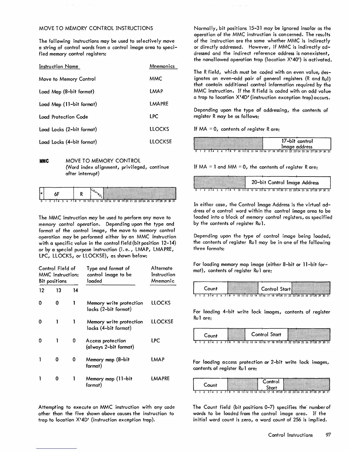
The MMC instruction may be used to perform
any
move to
memory control
operation.
Depending upon
the
type
and
format
of
the
control
image,
the
move to memory control
operation
may be performed
either
by
an
MMC instruction
with a
specific
value
in the control field (bit position 12-14)
or
by a special purpose instruction
(i.
e.,
LMAP,
LMAPRE,
LPC, LLOCKS, or LLOCKSE),
as
shown below:
Control Field
of
Type
and
format
of
Alternate
MMC instruction:
control image to be
Instruction
Bit
positions loaded
Mnemonic
12
13
14
0 0
Memory write
protection
LLOCKS
locks
(2-bit
format)
0
Memory write
protection
LLOCKSE
locks
(4-bit
format)
0 0
Access
protection
LPC
(always
2-bit
format)
0 0
Memory map
(8-bit
LMAP
format)
0 Memory map
(ll-bit
LMAPRE
format)
Attempting to
execute
an MMC instruction with
any
code
other
than
the
five shown
above
causes
the
instruction to
trap
to location X
'
4D' (instruction
exception
trap).
Normally,
bit
positions 15-31 may be ignored insofar as
the
operation
of the MMC instruction
is
concerned.
The results
of
the
instruction
are
the
same
whether
MMC
is
indirectly
or
directly
addressed. However,
if
MMC
is
indirectly
ad-
dressed
and
the
indirect
reference
address
is
nonexistent,
the
nonallowed
operation
trap
(location
X
'
40
'
)
is
activated.
The R
field,
which must be coded with
an
even
value,
des-
ignates an
even-odd
pair
of
general
registers
(R
and
Ru1)
that
contain
additional
control information required by
the
MMC instruction. If
the
R
field
is
coded with an odd
value
a
trap
to
location
X'4D'
(instruction
exception
trap) occurS.
Depending upon
the
type
of
addressing,
the
contents
of
register
R may be as follows:
If
MA
=
0,
contents
of
register
Rare:
If
MA
= 1 and
MM
=
0,
the
contents
of
register
Rare:
In
either
case,
the
Control Image Address
is
the
virtual
ad-
dress
of
a control word within
the
control image
area
to be
loaded
into a block of memory control registers, as
specified
by
the
contents of
register
Ru
1.
Depending upon
the
type
of
control image being
loaded,
the
contents of register
Ru
1 may
be
in
one
of
the following
three
formats:
For loading memory map image
(either
8-bit
or
11-bit
for-
mat),
contents
of
register
Ru
1
are:
For loading
4-bit
write
lock images, contents
of
register
Ru1
are:
For loading
access
protection
or
2-bit
write
lock images,
contents
of
register
Ru
1
are:
The
Count
field (bit positions
0-7)
specifies the'
numberof
words
to
be loaded from the control image
area.
If
the
initial
word count
is
zero,
a word count of 256
is
implied.
Control Instructions 97
 Loading...