TURN
OFF MODE
ALTERED
FLAG
The
following configuration
of
WD
is
used
to
reset
the
Mode
Altered
Flag
(PSWs
61) to 0:
STORE
IN
LOW
MAIN MEMORY
This instruction writes
into
main memory locations 0-31
(locations
0-15
shadowed by
the
general
purpose registers
and reserved locations). This
allows storing or changing the
Status
Stack
Pointer Doubleword in locations
0-1
and
the
default
Program Status Words (Status
Stack
is
empty) in
locations 2 through
4.
If
the
R fi e
Id
is
non zero,
the
contents of R
are
stored in
the
main memory location
identified
by bits
27-31.
TRAP
TO LOCATION X
'
47
1
This instruction causes
the
basic processors to trap
to
loca-
tion
X1471.
A
I~
__
~_
..
1..._
D
____
~~
__
D
..
~
:~
__
:~_..J
1...
....
I...~
:_:
..
:_
.. :
__
1..._:_
1\
IIII~
III
'I.~
IIV"",,,v..l'.;JV'
U,",.;J
I.;J
1'Yo',;)v,,",
ul
II.v
....
,.\"AI
•••
~
"""",,,",,'v
processor (or the associated PI). This
line,
when
true,
causes
the
basi c processors
to
trap
to
X
1471
(including
the
one
that
executes
the instruction).
WRITE
INTO
INTERNAL CONTROL
REGISTER
The following configuration
of
WD
is
used to write into
the
internal control (or
Q)
registers:
If
the
R field
is
nonzero,
the
contents of register
Rare
loaded in
the
control register, as
specified
by
the
IIQ
Ad-
dress" field (bit positions
27-31)
of
the
WD
instruction.
Except for
the
four Q addresses listed
below,
all
other
ad-
dresses
are
reserved:
Q Address
X
'
1D
'
X
'
1E
'
Significance
{
(Bits
00-13)
- Reserved.
(Bits
14-31) - Write into the "Branch
From"
program
counter.
{
(Bits
00 through 07) - Reserved.
(Bits
08
through 31) - Write
into
the
"Load
Device Address" register.
If
the
R field
is
zero,
the
specified
register
is
loaded with
all zeros.
Affected:
(E
L)
(R)
-
(EL)
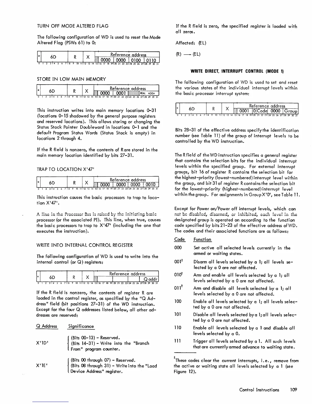
WRITE
DIRECT,
INTERRUPT
CONTROL
(MODE
1)
The following configuration of
WD
is
used to set and reset
the various states of
the
individual interrupt levels within
the basi c processor interrupt system:
Bits
28-31 of
the
effective
address specify
the
identification
number (see Table 11)
of
the group of interrupt levels to be
controlled by
the
WD
instruction.
The R field of
the
WD
instruction specifies a
general
register
that
contains
the
selection
bits for the individual interrupt
levels within
the
specified
group. For
external
interrupt
groups,
bit
16
of
register R contains
the
selection
bit for
the highest-priority (lowest-numbered) interrupt level within
the group, and
bit310f
register R contains the
selection
bit
for the lowest-priority (highest-numbered) interrupt level
within the group. For assignments in GroupX101,
see
Table 11.
Except for
Power
on/Power
off
interrupt levels, which
can
_~
..
I...~
..J:~_I...I_..J
..J:~
____
..J
__
:_I...~I...:
..
_..1
___
I...
1
____
1
:_
..
L_
IIVI
...,"'"
'-I
•
.;Juu.vu,
UlaUllllCU,
VI
IIII"IJ'I~U,
C\.I\,
...
II
I'C;;VIIIW'I
'11
Ille
designated group
is
operated
on
according
to
the
function
code
specified
by bits
21-23
of
the
effective
address
ofWD.
The codes
and
their
associated functions are as follows:
Code
000
100
101
110
111
Function
Set
active
all
selected
levels currently in
the
armed or
waiting
states.
Disarm
all
levels
selected
by a
1;
all
levels
se-
lected
by a 0
are
not
affected.
Arm
and
enable
all
levels
selected
by a
1;
all
levels
selected
by a 0
are
not
affected.
Arm
and
disable
all
levels
selected
by a
1;
all
levels
selected
by a 0
are
not
affected.
Enable
all
levels
selected
by a
1;
all
levels
selec-
ted by a 0
are
not
affected.
Disable
all
levels
selected
bya
l;all
levels
selec-
ted
by a 0
are
not
affected.
Enable
all
levels
selected
by a 1 and
disable
all
levels
selected
by a
O.
Trigger
all
levels
selected
by
a
1.
All such levels
that
are
currentlyarmed
advance
to
waiting
state.
tThese codes
clear
the
current interrupts,
i.
e.
I remove from
the
active
or
waiting
state
all
levels
selected
by a 1 (see
Figure 12).
Control Instructions
109