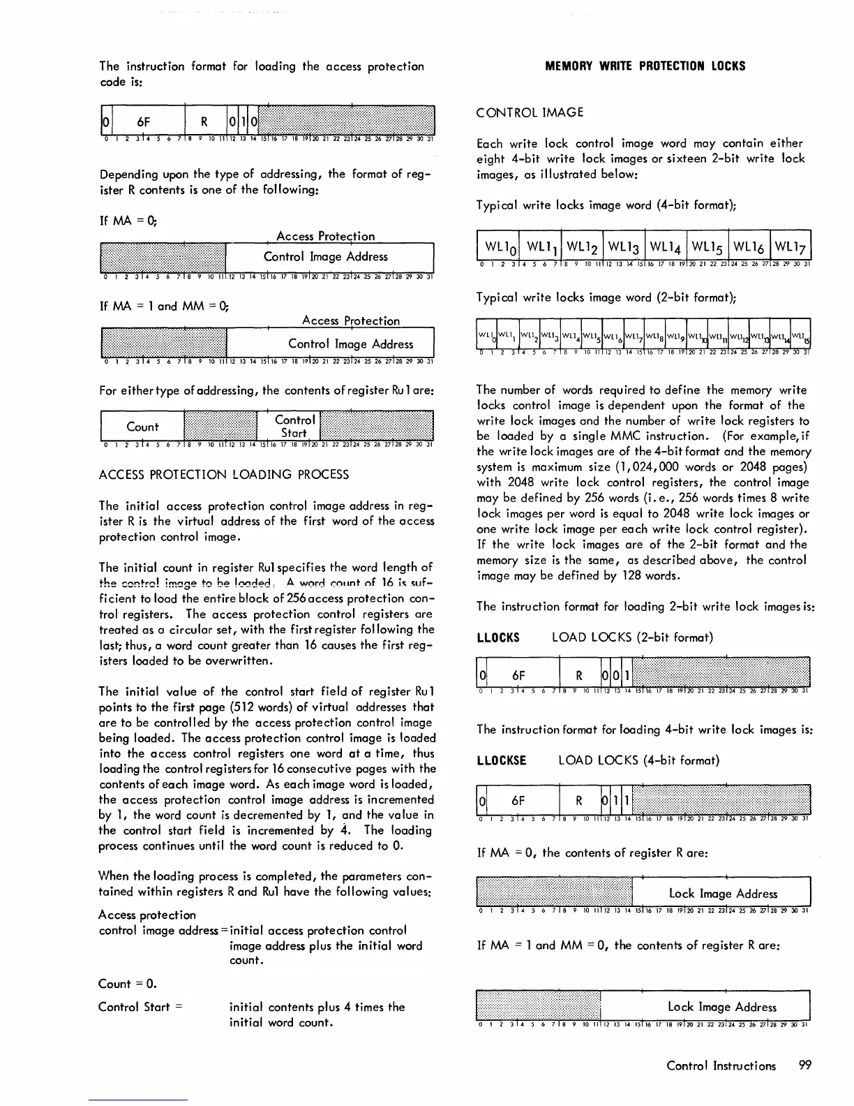
The instruction format for loading
the
access
protection
code
is:
Depending upon
the
type
of
addressing,
the
format
of
reg-
ister R
contents
is
one
of
the
following:
IfMA=O;
If
MA
= 1
and
MM
=
0;
For
eithertype
of
addressing,
the
contents
of
register
Ru
1
are:
ACCESS PROTECTION LOADING
PROCESS
The
initial
access
protection
control image address
in
reg-
ister R is
the
virtual
address
of
the
first word
of
the
access
protection
control image.
The
initial
count in register
Ru1
specifies
the
word length
of
~he
c~!"!~:-d
!m!:!ge
t~
be
!0!:!clecl
,A
"""rd
~ount
of
16
ic;
c;uf-
fi
cient
to load
the
entire
block
of
256
access
protection
con-
trol registers. The
access
protection
control registers
are
treated
as
a
circular
set,
with
the
first
register
fol lowing
the
last; thus, a word
count
greater
than
16
causes
the
first
reg-
isters loaded
to
be
overwritten.
The
initial
value
of
the
control start
field
of
register
Ru
1
points to
the
first
page
(512 words)
of
virtual
addresses
that
are
to
be
controlled
by
the
access
protection
control image
being
loaded.
The
access
protection
control image
is
loaded
into
the
access
control registers
one
word
at
a
time,
thus
loading
the
control registers for
16
consecutive
pages with
the
contents
of
each
image word. As
each
image word
is
loaded,
the
access
protection
control image address is incremented
by 1,
the
word
count
is
decremented
by 1,
and
the
value
in
the
control start field is incremented by
4.
The loading
process
continues
until
the
word
count
is
reduced
to
O.
When
the
loading process is
completed,
the
parameters
con-
tained
within registers
Rand
Ru1
have
the
following values!
Access
protection
control image address =
initial
access
protection
control
image address plus
the
initial
word
count.
Count
=
O.
Control
Start
=
initial
contents plus 4 times
the
initial word
count.
MEMORY
WRITE
PROTECTION
LOCKS
CONTROL
IMAGE
Each
write
lock control image word may
contain
either
eight
4-bit
write lock images
or
sixteen
2-bit
write lock
images, as
illustrated
below:
Typical
write
locks image word
(4-bit
format);
Typical
write
locks image word
(2-bit
format);
The number
of
words required
to
define
the
memory write
locks control image is
dependent
upon
the
format
of
the
write
lock images and
the
number
of
write
lock registers to
be
loaded
by a
single
MMC
instruction.
(For example,
if
the
write lock images
are
of
the
4-bit
format
and
the
memory
system
is
maximum
size
(1,024,000
words
or
2048 pages)
with 2048 write lock control
registers,
the
control image
may
be
defined
by 256 words
(i.
e.,
256 words times 8 write
lock images
per
word
is
equal
to
2048 write lock images
or
one
write
lock image
per
each
write
lock control
register).
If
the
write lock images
are
of
the
2-bit
format
and
the
memory
size
is
the
same,
as
described
above,
the
control
image may
be
defined
by 128 words.
The instruction format for loading
2-bit
write
lock images
is:
LLOCKS
LOAD LOC
KS
(2-bit
format)
The instruction format for loading
4-bit
write
lock images is:
LLOCKSE
LOAD LOC
KS
(4-bit
format)
If
MA
=
0,
the
contents
of
register
Rare:
lock
lmag~
Address
If
MA
= 1
and
MM =
0,
the
contents
of
register
Rare:
Control Instructions 99
 Loading...