4.
Each
unit-record
controller
(internal or external)
requires one
I/o
subchannel per
each
unit
record
de-
vice
attached,
up
to
a maximum of
eight.
5.
The maximum number of internal
device
controllers
within
an
MIOP
is
eight
(where a
unit-record
device
controller
is
equivalent
to
one,
regardless of the
number of assigned subchannels).
6. Any
I/o
subchannel not assigned
to
an
internal
de-
vice
controller
may be assigned
to
an
external
device
controller.
Thus, if
an
MIOP has no internal
device
controller,
all
16
I/O
subchannels may be assigned
to
external
device
controllers.
INPUT
jOUTPUT
PROCESSOR
[lOP)
FUNDAMENTALS
This
section
contains
general information, programming
concepts,
and
definition
of terms pertaining
to
I/o
oper-
ations
performed by
Input/Output
Processors (i.
e.,
MIOP).
The
large
variety
of
I/O
devices
which may be used with
these
lOPs
precludes a
detailed
or exhaustive
descrip-
tion of features which
are
unique
to
each
device.
like-
wise, a
general
reference"
Refer
to
an
appropriate
Xerox
peripheral
reference
manual" is made rather
than
citing
specific
manuals.
Within this manual, the following terminology is used
to
differentiate
the
hierarchy of control during
an
I/o
operation: The
BP
executes
instructions, the lOPs
exe-
cute
commands,
and
the
device
controller/device
exe-
cute
orders.
COMMAND
LIST
Each
I/O
operation
performed by
an
lOP
must be
defined
by
a command list. The
characteristics
and requirements
of a command iist
are
as foiiows:
1.
It
is normally
created
by a BP-executed program
prior
to
the
time
that
the
defined
I/O
operation
is
ini-
tiated.
It
must reside in main memory when the
I/O
operation
is
initiated
and subsequently
executed.
2.
Depending upon various programming considerations,
the
command list may be
contained
within one or more
areas
of memory and
each
area
may be comprised of
one
or more
I/o
command doublewords (lOCOs).
3.
Command list
continuity
between lOCOs
relating
to
the
same logical record or to
the
same logical
file
may
be
specified
(see
"Data
Chain
Flag
ll
and
IICom-
mand
Chain
Flag
ll
under 1I0perationai 10CDslI). Com-
mand list
continuity
between
portions of a command
list
located
in different
areas
of main memory may
126
Input/Output
Processor (lOP) Fundamenta
Is
be
accomplished by including a control
lOCO
within
the
command list (see
II
Transfer in Channel
ll
under
"Control
10CDsll).
4.
Each
lOCO
is comprised of two words in contiguous
memory word locations. The first word must be stored
in
an
even
memory word
location
and
the second
word must be stored in
the
next "consecutive (odd)
memory word
location.
Each
lOCO
is
either
an
operational
lOCO
or a control
lOCO
and
contains
coded
parameters
to
define
either
a
complete
I/o
operation
or
an
integral portion of
an
I/O
operation.
(See"
Operational
lOCO"
and
"Control
lOCO"
for
further
detai
Is.
)
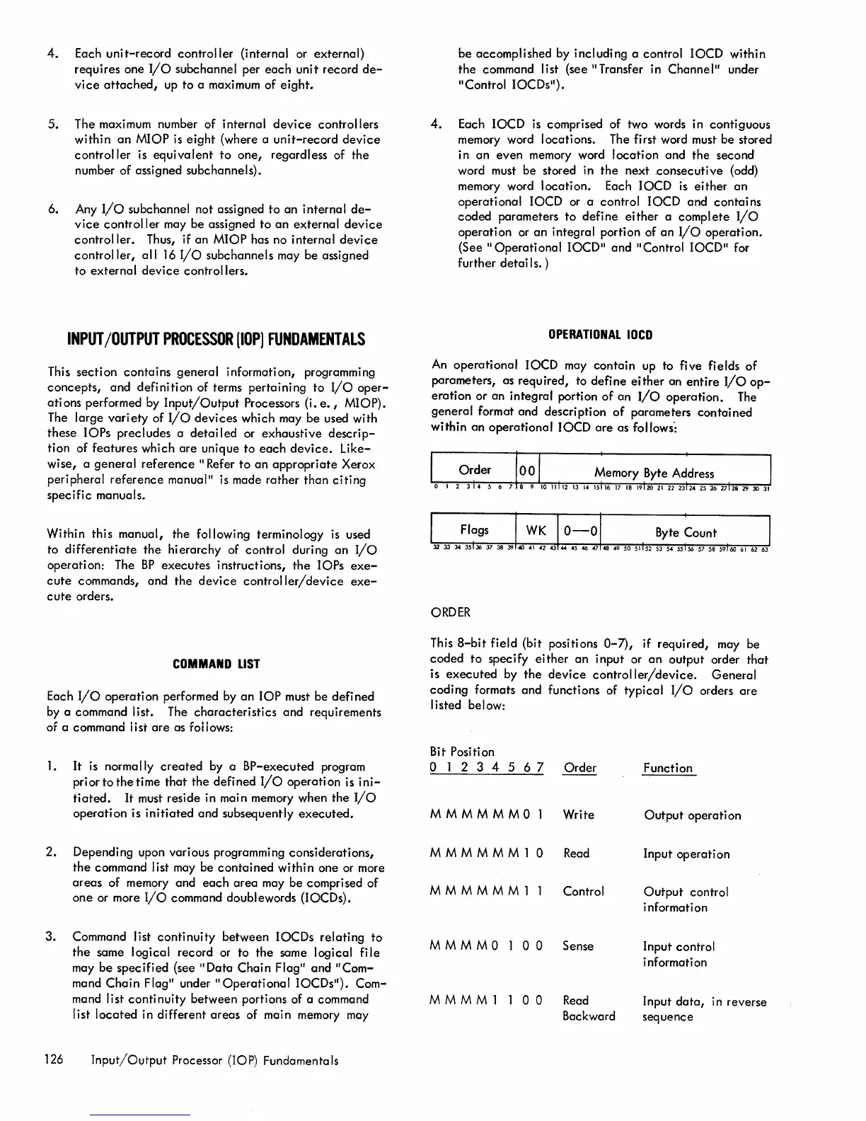
OPERATIONAL
lOCO
An
operational
lOCO
may contain up to five fields
of
parameters, as required, to
define
either
an
entire
I/O
op-
eration
or an integral portion
of
an
I/o
operation.
The
general
format and description
of
parameters
contained
within
an
operational
lOCO
are
as
follows":
ORDER
This
8-bit
field (bit positions 0-7), if
required,
may be
coded
to
spec ify ei ther
an
input or
an
output order
that
is
executed
by
the
device
controller/device.
General
coding
formats and functions of typical
I/o
orders
are
I isted below:
Bit
Position
o 1 2 3 4 5 6 7
Order
M M M M M
MOl
Write
M M M M M M 1
0 Read
M M M M M M 1 1 Control
M M M
MOl
0 0 Sense
M M M M 1 1
0 0
Read
Backward
Function
Output
operati on
Input operati on
Output
control
i nformat i on
Input control
information
Input
data,
in reverse
sequence