POLP and
POLR
INSTRUCTIONS
The R field of these two instructions always
specifiesa
gen-
eral register (including register
0)
that
may
receive
up
to
16 bits of fault status information
from
an
addressed
BP
or
MIOP. Each bit indicates the presence
(1)
or absence
(O)
of a specific fault condition within
the
polled processor
(as listed in Table
C-1).
Note
that
the
information
represented by a particular bit is also
dependent
upon
the type of processor polled (e.
g.,
bit
18
may
indicate
a
memory parity error
in
the
BP
or a control
check
fault
within an MIOP).
Ala
INSTRUCTION
For this instruction, if the R field has a
value
of
0,
no
status information is requested nor loaded.
If
the
R field
has a value of X
l
l
1
through
X'F',
the
specified register may
receive
one word of
I/o
information pertaining
to
an
I/O
interrupt.
Device and Device Controller Status Byte.
Bits
0-7
of the
status word obtained by
an
AIO instruction from a respond-
ing
I/O
subsystem
are
unique
to
the
device
and
device
controller. These bits
are
described in
the
applicable
pe-
ripheral
device
reference manual.
lOP
Status Byte.
Bits
8-15
indicate
the
presence (1) or
absence
{O}
of various operation errors and interrupts
that
may have occurred during
an
I/O
operation. The functions
of individual bits within the
lOP
Status Byte
are
described
in Table 18.
Table 19 is a summary description of
the
Device/Device
Controller Status Byte and
the
lOP
Status Byte.
Bits 16-18. These bits of
the
AIO response
are
reserved.
To
ensure program compatibility with any enhancements
{software
and/or
hardware},
it
is recommended
that
these
bits
be
treated
as indeterminate and not used (i.
e.,
masked).
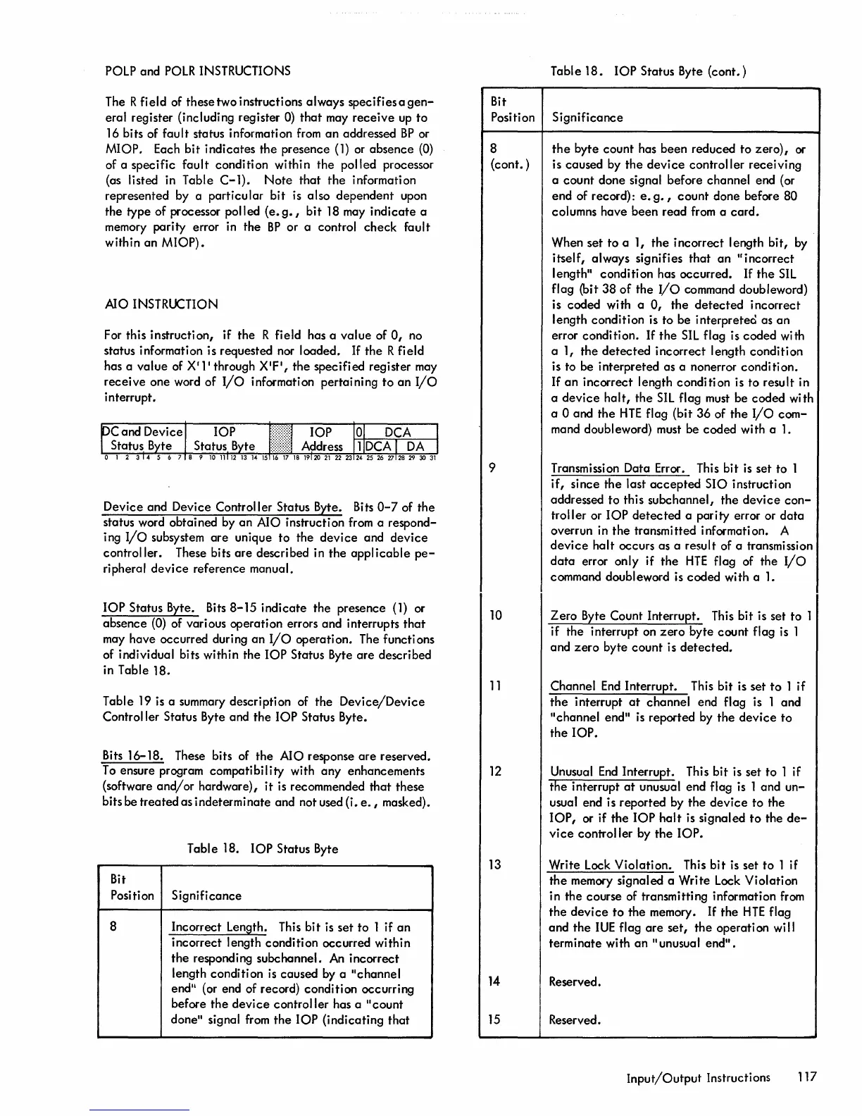
Table 18.
lOP
Status Byte
Bit
Position Significance
8
Incorrect Lenlilth. This
bit
is set
to
1 if
an
incorrect length condition occurred within
the
responding subchannel.
An
incorrect
length condition
is
caused
by
a "channel
end
ll
(or end of record) condition occurring
before
the
device
controller has a
"count
done" signal
from
the
lOP
(indicating
that
Bit
Position
8
(cont. )
9
10
11
12
Table
18.
lOP
Status Byte
(cont.)
Significance
the
byte count has been reduced to zero), or
is caused by
the
device
controller receiving
a
count
done signal before channel end (or
end of record):
e.
g.,
count
done before 80
columns have been
read
from a
card.
When set
to
a 1,
the
incorrect length bit,
by
itself, always signifies
that
an
"incorrect
length" condition has occurred.
If
the
SIL
flag (bit
38
of
the
I/O
command doubleword)
is coded with a
0,
the
detected
incorrect
length condition is to be interpreted as
an
error condition.
If
the
SIL
flag is coded with
a 1, the
detected
incorrect length condition
is to be interpreted as a nonerror condition.
If
an
incorrect length
condition
is to result in
a
device
halt,
the
SIL
flag must be coded with
a 0 and
the
HTE
flag (bit
36
of
the
I/O
com-
mand doubleword) must be coded with a
1.
Transmission Data Error. This bit is set to 1
if,
since
the
last
accepted
SIO instruction
addressed to this subchannel,
the
device
con-
troller or
lOP
detected
a parity error or
data
overrun in
the
transmitted information. A
device
halt
occurs as a result of a transmission
data
error only if
the
HTE
flag of the
I/o
command doubleword is coded with a
1.
Zero Byte Count Interrupt. This bit is set to 1
if the interrupt on
zero
byte count flag is 1
and
zero
byte
count
is
detected.
Channel
End
Interrupt. This bit is set
to
1 if
the
interrupt
at
channel end flag is 1 and
"channel end" is reported
by
the
device to
the
lOP.
Unusual
End
Interrupt. This bit is set
to
1 if
the
interrupt
at
unusual end flag is 1 and
un-
usual end is reported by
the
device
to the
lOP,
or if
the
lOP
halt
is signaled
to
the
de-
vi
ce
control I er by
the
lOP.
13
Write Lock Violation. This
bit
is set to 1 if
the
memory signaled a Write Lock Violation
in the course of transmitting information
from
the
device to
the
memory.
If
the
HTE
flag
and
the
I
UE
flag
are
set,
the
operati
on
wi
II
terminate with
an
"unusual
end".
14
Reserved.
15
Reserved.
Input/Output
Instructions 117
 Loading...


