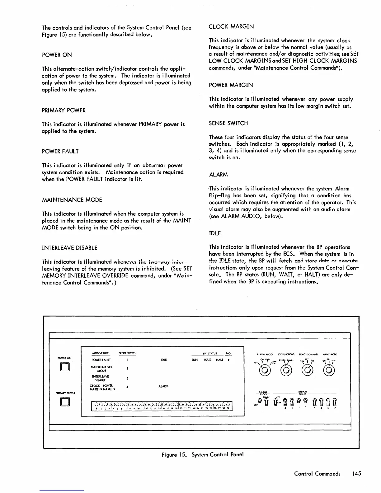
The controls
and
indicators of the System Control Panel (see
Figure 15)
are
functioanlly described
below.
POWER
ON
This
alternate-action
switch/indicator
controls
the
appli-
cation
of power
to
the
system. The
indicator
is illuminated
only when
the
switch has
been
depressed and power is being
applied
to
the
system.
PRIMARY
POWER
This
indicator
is illuminated whenever
PRIMARY
power is
applied
to
the
system.
POWER
FAULT
This indicator is illuminated only if
an
abnormal power
system
condition
exists.
Maintenance
action
is required
when
the
POWER
FAULT
indicator
is
lit.
MAINTENANCE MODE
This indicator is illuminated when
the
computer system is
placed
in the
maintenance
mode as
the
result of
the
MAINT
MODE switch being in
the
ON
position.
INTERLEAVE
DISABLE
_I.
•
I.
~
•
_II
• • I I
.,
..
I
nls
lnaicarOf
IS
"Iumtnareo
wnt:rtt:vt:I
HIt:
IWU-WUY
IIII~-
leaving
feature
of
the
memory system is inhibited. (See
SET
MEMORY
INTERLEAVE
OVERRIDE
command,
under"
Main-
tenance
Control Commands".)
MOOEII'AULT
~
PONEION
POWER
FAULT
I
IDLE
RUN
0
MAINTENA"'CE
2
MODE
INTERLEAVE
DISABLE
3
CLOCK
POWER
4
ALARM
MARGIN
MARGIN
-.ul'P'ONER
CLOCK MARGIN
This
indicator
is illuminated whenever
the
system
clock
frequency is
above
or below
the
normal
value
(usually as
a result of
maintenance
and/or
diagnostic
activities;
see
SET
LOW CLOCK MARGINS
and
SET
HIGH CLOCK MARGINS
commands, under
"Maintenance
Control Commands").
POWER
MARGIN
This
indicator
is illuminated whenever
any
power supply
within
the
computer system has its low margin switch set.
SENSE
SWITCH
These four indicators display the status of
the
four sense
switches. Each
indicator
is
appropriately
marked (1,
2,
3,
4)
and
is illuminated only when
the
corresponding sense
switch is on.
ALARM
,This indicator is illuminated whenever
the
system Alarm
flip-flog
has
been
set,
signifying
that
a condition has
occurred which requires
the
attention
of
the
operator. This
visual alarm may also
be
augmented with
an
audio
alarm
(see
ALARM
AUDIO, below).
IDLE
This
indicator
is
illuminated whenever
the
BP
operations
have
been
interrupted by the ECS. When
the
system
is
in
the
!DLE
5t~te,
the
BP
'M'!!!
fekh
~!",!d
c:t(\re
data
(\r
p.xp.r.lIte
instructions only upon request from
the
System Control
Con-
sole.
The
BP
states (RUN, WAIT, or
HALT)
are
only
de-
fined when
the
BP
is
executing
instructions.
IP
STATUS
NO.
ALARM. AUOIO
see
fUNCTIONS
R£MOTECHA.~L
....
NY
MODE
WAIT
HALT
•
Of~,l\
",~
/r'Err
EN,O)SAaf.
OFf
"\ii"T
~
I
yo
@@
@
@
-
SINGLf_
DISPlAY
ClOCK
SflfCT
'
......
0
ti:U~@@
I
\."")
1)\.)(?t:)~-:'()~J~:i..Jl)l)~-}l:'()O~)OOGI()I)()(")r)()
Gt)~-II./l)\"")
1
",,@
tl
l1f1f1fl
• 1 2 1 • S 6 7 B •
10
n
12
13
..
IS
16
17
IB
..
20
21
22 13
2'
ZS
21>
27
2B
29
JO
31
•
I
2
1
.
S
6
1
Figure 15. System Control Panel
Control Commands 145
 Loading...