configuration.
This is,
any
configuration
other
than
100,
010,
101, 001,
or
011.
4.
The
set
of
operations,
primarily doubleword
instruc-
tions,
that
yield
an
unpredictable
result when
an
in-
correct
register
is
specified;
this type
of
fault
is
called
"invalid
register
designation"
and
includes
the
follow-
..
•
II
t
Ing instructions •
Odd
Register
Specified
Add Doubleword (AD)
Subtract
Doubleword (SD)
Floating
Add
Long
(FAL)
Floating
Subtract
Long
(FSL)
Floating
Multiply
Long
(FML)
Floating Divide
Long
(FDL)
Move to Memory Control (MMC)
TRAP
CONDITION
CODE
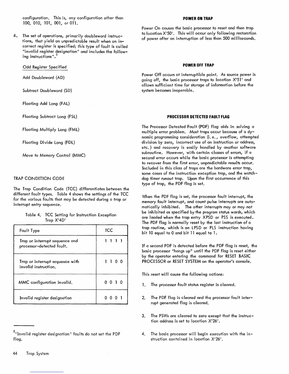
The Trap
Condition
Code (TCC)
differentiates
between the
different
fault
types. Table 4 shows
the
settings
of
the
TCC
for
the
various faults
that
may be
detected
during a trap
or
interrupt
entry
sequence.
Table
4.
TCC
Setting for Instruction Exception
Trap
X
'
4D
'
Fault
Type
TCC
Trap
or
interrupt
sequence
and
1
1 1
processor-detected
fault.
T
rap
or
interrupt
sequence
wi
th
1
1
0
invalid
instruction.
MMC
configuration
invalid.
0
0
1
Invalid
register
designation
0
0 0
tllInvalid
register
designation"
faults do not
set
the
PDF
flag.
44 Trap System
1
0
0
1
POWER
ON
TRAP
Power
On
causes
the
basi c processor to
reset
and
then
trap
to
location
X
'
50
'
. This wi II
occur
only
following restoration
of
power
after
an interruption
of
less than 500
mi
Iliseconds.
POWER
OFF
TRAP
Power
Off
occurs
at
interruptible
point.
As
source power
is
going off, the basic processor traps to location X
'
51
1
and
allows
sufficient
time for
storage
of
information before
the
system becomes
inoperable.
PROCESSOR
DETECTED
FAULT
FLAG
The Processor
Detected
Fault
(PDF) flag
aids
in solving a
multiple
error
problem. Most traps
occur
because
of a
dy-
namic programming consideration (i. e., overflow,
attempted
division by
zero,
incorrect
use
of
an instruction
or
address,
etc.)
and
recovery
is easi
Iy
handled
by
another
software
subroutine.
However,
with
certain
classes of errors, if a
second
error
occurs
while
the basi c processor is
attempting
to
recover
from the first
error,
unpredictable
results
occur.
Included in this class
of
traps
are
the
hardware
error
trap,
some cases
of
the
instruction
exception
trap,
and the
watch-
dog timer runout trap. Upon
the
first
occurrence
of
this
type
of
trap,
the
PDF
flag
is
set.
When the
PDF
flag
is
set,
the
processor
fault
interrupt,
the
memory
fault
interrupt,
and
count
pulse interrupts
are
auto-
matically
inhibited.
The
other
interrupts
mayor
may not
be
inhibited
as
specified
by
the
program status words, which
are
loaded when the trap
entry
X
PSD
or
PSS
is
executed.
The
PDF
flag
is
normally reset by the last instruction
of
a
trap
routine,
which
is
an
LPSD
or
PLS
instruction having
bit
10
equal
to 0
and
bit
11
equal
to
1.
If
a second
PDF
is
detected
before
the
PDF
flag is reset, the
basic
processor IIhangs up" until the
PDF
flag is reset
either
by the
operator
entering
the command for
RESET
BASIC
PROCESSOR
or
RESET
SYSTEM
on
the
operator's
console.
This
reset
wi"
cause
the
following
actions:
1. The processor
fault
status register is
cleared.
2. The
PDF
flag is
cleared
and
the
processor
fault
inter-
rupt
generated
flag
is
cleared.
3.
The
PSWs
are
cleared
to
zero
except
that
the
instruc-
tion address is
set
to
location
X'26
1
•
4. The
basic
processor will begin
execution
with the
in-
struction
contained
in
location
X'26
1
•