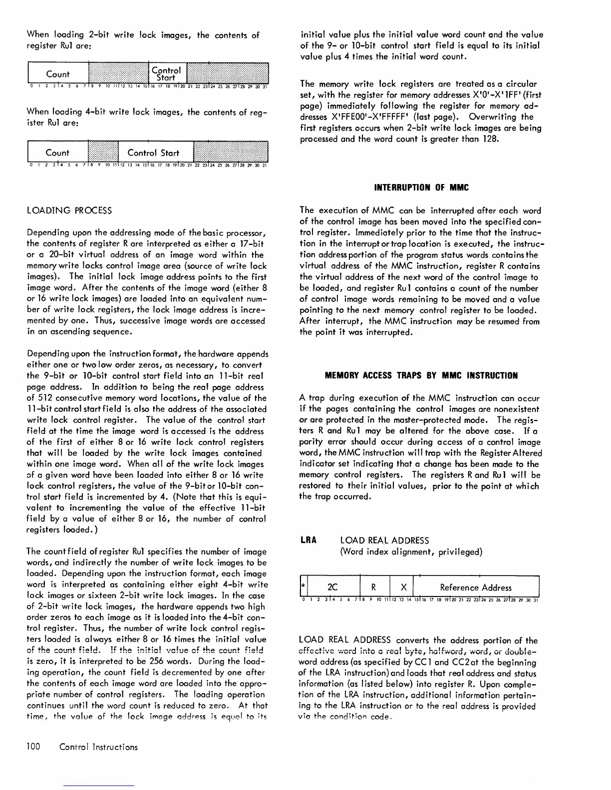
When loading
2-bit
write lock images,
the
contents
of
register
Ru1
are:
When loading
4-bit
write lock images,
the
contents of
reg-
ister
Ru1
are:
LOADING
PROCESS
Depending upon
the
addressing mode
of
the
basic
processor,
the
contents
of
register R
are
interpreted
as
either
a
17-bit
or
a
20-bit
virtual
address
of
an
image word within
the
memory
write
locks control image
area
(source of write lock
images). The
initial
lock image address points to the first
image word.
After
the
contents
of
the
image word
(either
8
or
16
write lock images)
are
loaded
into an
equivalent
num-
ber
of
write
lock registers,
the
lock image address
is
incre-
mented by
one.
Thus, successive image words
are
accessed
in an
ascending
sequence.
Depending upon
the
instruction format, the hardware appends
either
one
or two low order
zeros,
as
necessary,
to convert
the
9-bit
or
lO-bit
control start field into
an
11-bit
real
page
address.
In
addition
to being
the
real
page address
of
512
consecutive
memory word
locations,
the
value
of the
11-bit
control start field
is
also the address
of
the
associated
write
lock control register. The
value
of
the
control start
field
at
the
time the image word
is
accessed
is
the
address
of
the
first
of
either
8 or
16
write lock control registers
that
will be loaded by the write lock images
contained
within
one
image word. When
all
of
the
write lock images
of a
given
word have been loaded into
either
8
or
16
write
lock
control registers,
the
val ue
of
the
9-bit
or lO-bit
con-
trol
start
field
is
incremented by
4.
(Note
that
this
is
equi-
valent
to
incrementing
the
value
of
the
effective
11-bit
field
by a
value
of
either
8
or
16,
the
number of control
registers
loaded.)
The
count
field
of
register
Ru1
specifies the number of image
words,
and
indirectly
the
number
of
write
lock images to
be
loaded.
Depending upon
the
instruction format,
each
image
word
is
interpreted
as
containing
either
eight
4-bit
write
lock images
or
sixteen
2-bit
write
lock images.
In
the
case
of
2-bit
write
lock images,
the
hardware appends two high
order zeros to
each
image as it
is
loaded into the
4-bit
con-
trol
register.
Thus,
the
number
of
write lock control
regis-
ters loaded
is
always
either
8 or
16
times
the
initial
value
of the count
field.
If
the :nitia! "/c!ue of the
count
field
is
zero,
it
is
interpreted
to be 256 words. During
the
load-
ing
operation,
the
count field
is
decremented
by
one
after
the
contents
of
each
image word
are
loaded into the
appro-
priate
number of control registers. The loading
operation
continues until
the
word count
is
reduced to
zero.
At
that
time,
the
vallie of
the
lock image
address
is
equol
to its
100 Control Instructions
initial
value
plus
the
initial
value
word count
and
the
value
of
the
9-
or
lO-bit
control start field
is
equal to its
initial
value
plus 4 times the
initial
word
count.
The memory write lock registers
are
treated
as
a
circular
set,
with
the
reg ister for memory addresses X
IOI_X
I 1
FF
I (first
page)
immediately following
the
register for memory
ad-
dresses X'FFEOO'-X'FFFFF' (last
page).
Overwriting
the
first registers occurs when
2-bit
write lock images
are
being
processed
and
the
word
count
is
greater
than 128.
INTERRUPTION
OF
MMC
The
execution
of MMC can be interrupted
after
each
word
of
the
control image has been moved into
the
specified
con-
trol
register.
Immediately prior to
the
time
that
the
instruc-
tion
in
the
interrupt
or
trap
location
is
executed,
the
instruc-
tion address portion of the program status words contains the
virtual
address of
the
MMC
instruction,
register R contains
the
virtual
address
of
the
next
word
of
the
control image to
be
loaded,
and
register
Ru
1 contains a count
of
the
number
of
control image words remaining to be moved and a
value
pointing
to
the
next
memory control register to be
loaded.
After
interrupt,
the
MMC instruction may be resumed from
the
point
it
was
interrupted.
MEMORY
ACCESS
TRAPS
BY
MMC
INSTRUCTION
A
trap
during
execution
of
the MMC instruction can
occur
if
the
pages
containing
the
control images
are
nonexistent
or
are
protected
in
the
master-protected
mode. The
regis-
ters
Rand
Ru
1 may be a Itered for
the
above
case.
If
a
parity
error should
occur
during
access
of a control image
word, the MMC instruction
wi"
trap with
the
Register
Altered
indicator
set
indicating
that
a
change
has been made to
the
memory control registers. The registers
Rand
Ru
1 will be
restored to
their
initial
values,
prior to
the
point
at
which
the
trap
occurred.
LRA
LOAD
REAL
ADDRESS
0Nord index al ignment,
privileged)
LOAD
REAL
ADDRESS
converts
the
address portion
of
the
effective
'.vOid
into a real
byte,
halfword, word,
or
double-
word address
{as
specified
byCC1
and
CC2at
the beginning
of
the
LRA
instruction}
and
loads
that
real address and status
information (as listed below) into register
R.
Upon
comple-
tion
of
the
LRA
instruction,
additional
information
pertain-
ing to
the
LRA
instruction or to the real address
is
provided
vio
the
conditio,.,
code.

 Loading...


