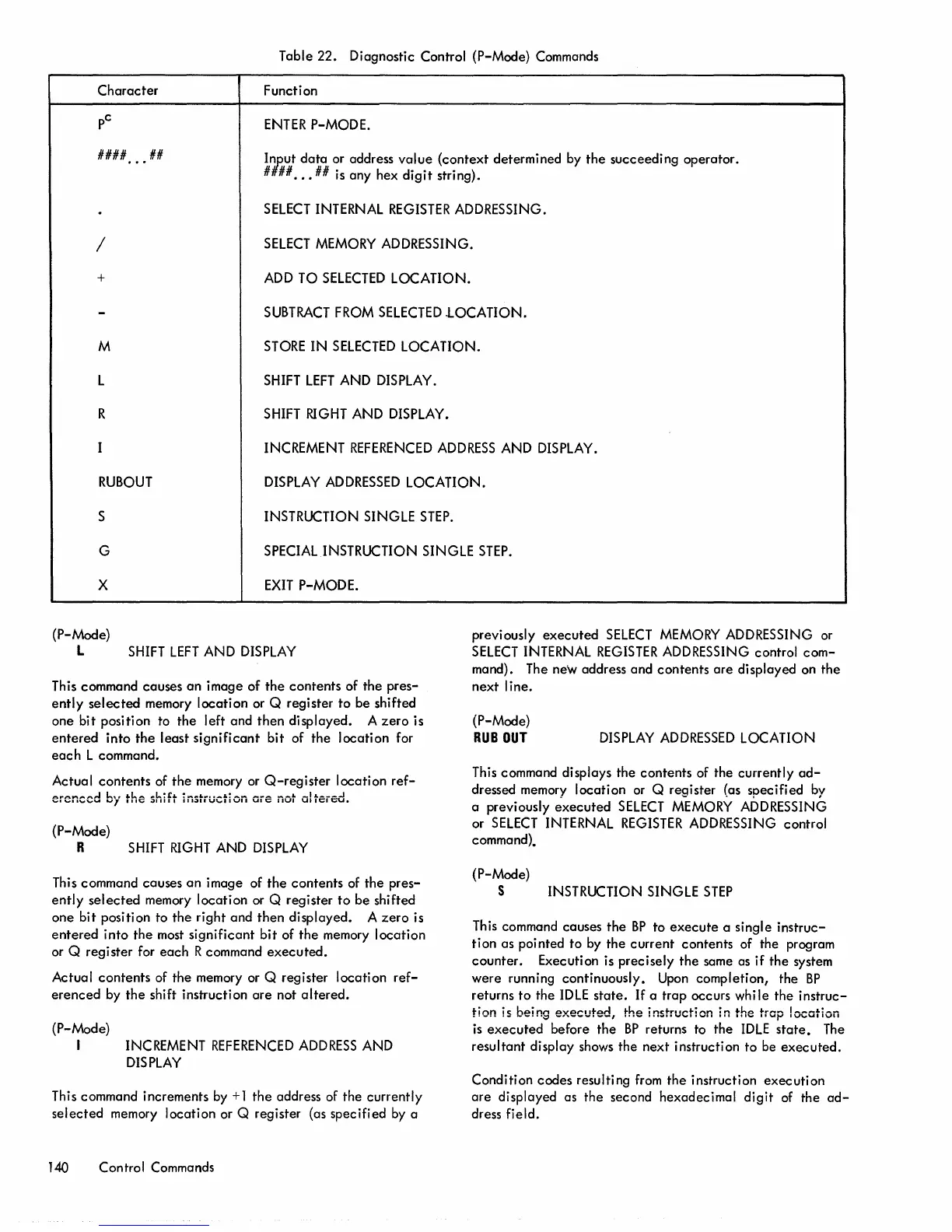
Table 22. Diagnostic Control (P-Mode) Commands
Character
Function
ENTER
P-MODE.
####
•••
##
Iihut
data
or
address value (context determined
by
the succeeding operator.
#
##
•••
##
is
any hex digit string).
SELECT
INTERNAL
REGISTER
ADDRESSING.
/
SELECT
MEMORY
ADDRESSING.
+
ADD
TO
SELECTED
LOCATION.
SUBTRACT
FROM
SELECTED
.LOCATION.
M
STORE
IN
SELECTED
LOCATION.
L
SHIFT
LEFT
AND
DISPLAY.
R
SHIFT
RIGHT
AND
DISPLAY.
INCREMENT
REFERENCED
ADDRESS
AND
DISPLAY.
RUBOUT
DISPLAY
ADDRESSED
LOCATION.
S INSTRUCTION SINGLE
STEP.
G
SPECIAL
INSTRUCTION SINGLE
STEP.
x
EXIT
P-MODE.
(P-Mode)
L
SHIFT
LEFT
AND
DISPLAY
This command causes an image of the contents of the pres-
ently selected
memory
location
or
Q register to be shifted
one bit position
to
the left and then displayed. A zero is
entered into the least significant bit of the location for
each L command.
Actual contents
of
the
memory
or
Q-register
location
ref-
erenced b,' the shift iiistiuction
QiS
not altsred.
(P-Mode)
R
SHIFT
RIGHT
AND
DISPLAY
This
command causes an image of the contents
of
the pres-
ently selected
memory
location
or
Q register to be shifted
one bit position to the right and then displayed. A zero
is
entered into the
most
significant bit of the
memory
location
or
Q register for each R command executed.
Actual contents
of
the
memory
or
Q register location
ref-
erenced
by
the shift instruction are not altered.
(P-Mode)
I
INCREMENT
REFERENCED
ADDRESS
AND
DISPLAY
This command increments
by
+ 1 the address
of
the currently
selected
memory
location or Q register (as specified
by
a
140
Control Commands
previously executed
SELECT
MEMORY
ADDRESSING
or
SELECT
INTERNAL
REGISTER
ADDRESSING
control com-
mand).
The
new address and contents are displayed
on
the
next line.
(P-Mode)
RUB
OUT
DISPLAY
ADDRESSED
LOCATION
This
command displays the contents
of
the currently
ad-
dressed
memory
location
or
Q register (as specified
by
a previously executed
SELECT
MEMORY
ADDRESSING
or
SELECT
INTERNAL
REGISTER
ADDRESSING
control
command).
(P-Mode)
S INSTRUCTION SINGLE
STEP
This
command causes the
BP
to execute a single instruc-
tion as pointed to
by
the current contents of the program
counter. Execution
is
precisely the same
as
if the system
were running continuously.
Upon
completion, the
BP
returns to the
IDLE
state.
If
a trap occurs
whi
Ie
the instruc-
tion
is
being executed, the instruction in the trap location
is
executed before the
BP
returns to the
IDLE
state.
The
resultant display
shows
the next instruction to
be
executed.
Condition codes resulting
from
the instruction execution
are displayed as the second hexadecimal digit
of
the
ad-
dress field.