Input Printout
Function
appropriate
control i nformati on to perform
mai
ntenance
or
diagnostic
functions, such as halting
and
resetting
the
basic processor, setting address hold, and
activating
vari-
ous
fault
detection
controls. During normal operations
it
should not be necessary
to
access
this word. The
contents
of
the
Processor Control Word
are
not
affected
by
either
processor or system reset, but
are
automatically
set
to
zero
(default
condition) during power-on sequencing and
by
the
SUPER
RESET
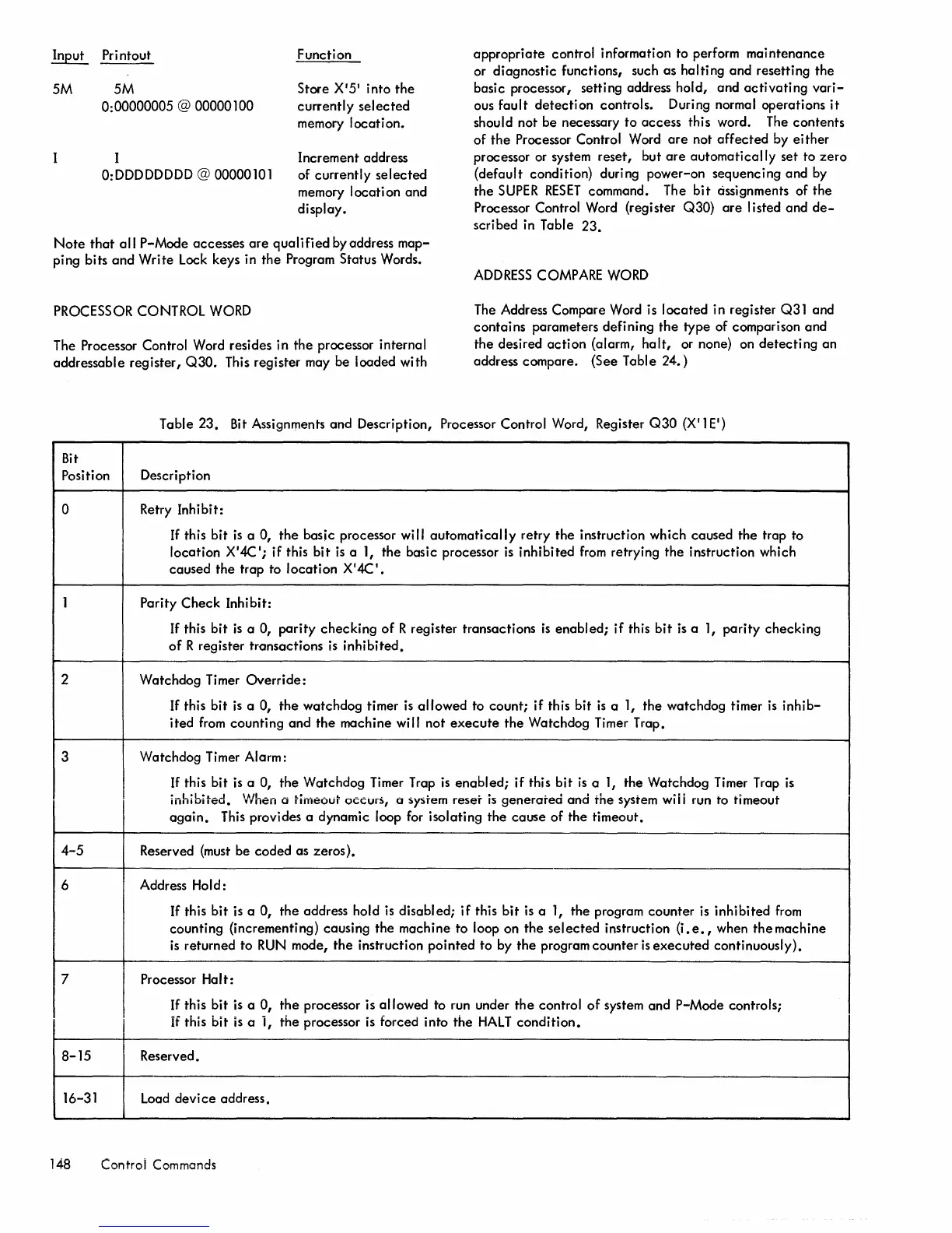
command. The
bit
assignments of the
Processor Control Word (register
Q30)
are
listed
and
de-
scribed in Table
23.
5M 5M
0: 00000005 @ 00000100
Store
X'5'
into
the
currently
selected
memory
location.
I
Increment address
O:DDDDDDDD
@ 00000101
of
currently
selected
memory
location
and
display.
Note
that
all
P-Mode accesses
are
qualified
by address
map-
ping bits
and
Write
Lock keys in
the
Program Status Words.
ADDRESS
COMPARE
WORD
PROCESSOR CONTROL
WORD
The Address Compare Word is
located
in register Q31 and
contains
parameters defining
the
type of comparison
and
the
desired
action
{alarm,
halt,
or none} on
detecting
an
address compare. (See Table
24.)
The Processor Control Word resides in the processor internal
addressable
register,
Q30.
This register may be loaded with
Table
23.
Bit
Assignments and Description, Processor Control Word, Register
Q30
(X' 1 E')
Bit
Position Description
0 Retry Inhibit:
If
this bit
is
a 0,
the
basic processor will
automatically
retry
the
instruction which caused
the
trap to
location X
'
4C';
if this
bit
is
a
1,
the
basic processor
is
inhibited
from
retrying
the
instruction which
caused
the
trap to
location
X'4C'.
1 Parity
Check
Inhibit:
If
this
bit
is
a 0,
parity
checking
of
R register transactions
is
enabled;
if
this
bit
is
a
1,
parity
checking
of
R register transactions
is
inhibited.
2 Watchdog Timer
Override:
If this
bit
is
a 0,
the
watchdog timer
is
allowed
to count;
if
this
bit
is
a
1,
the watchdog timer
is
inhib-
ited
from
counting and
the
machine will not
execute
the
Watchdog Timer Trap.
3
Watchdog Timer
Alarm:
If
this bit
is
a 0, the Watchdog Timer Trap
is
enabled;
if
this
bit
is
a
1,
the Watchdog Timer Trap
is
~_L~L!L_.J
1III1IUIIC::U.
When a rirneour
occurS,
(J
sy:)rem
re:)er
is
generated
and
the
system
wi
i i run to timeout
again.
This provides a dynamic loop for isolating
the
cause
of
the
timeout.
4-5
Reserved (must
be
coded
as zeros).
6 Address
Hold:
If
this
bit
is a 0,
the
address hold is disabled;
if
this
bit
is a 1, the program
counter
is inhibited
from
counting (incrementing) causing the machine to loop on
the
selected
instruction (i.
e.,
when
the
machine
is
returned to
RUN
mode,
the
instruction
pointed
to
by
the
program
counter
is
executed
continuously).
7
Processor
Ha
It:
If
this bit
is
a
0,
the
processor is
allowed
to run under
the
control
of
system
and
P-Mode controls;
if this
bit
is
a
i,
the
processor
is
forced into
the
HALT
condition.
8-15
Reserved.
16-31
Load
device
address.
148 Control Commands
 Loading...