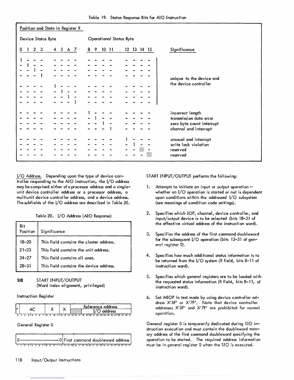
Table
19.
Status Response
Bits
for AIO Instruction
Position and State in Register R
Device
Status Byte
Operational
Status Byte
o
2 3 4 5 6 7 8 9
10
11
12
13
14 15
Significance
I/O
Address. Depending upon
the
type of
device
con-
troller
responding
to
the AIO instruction,
the
I/O
address
may be comprised
either
ofa
processor address and a
single-
unit
device
controller address or a processor address, a
multiunit
device
controller address, and a
device
address.
The subfields of
the
I/O
address
are
described in Table
20.
Table
20.
I/O
Address (AlO Response)
Bit
Position
Significance
18-20
This field contains
the
cluster address.
21-23
This field contains
the
unit address.
24-27
This field contains all ones.
28-31
This field
contains
the
device
address.
SIO
START
INPUT/OUTPUT
(Word index alignment, privileged)
Instruction Register
Genera
I
Reg
i ster 0
118
Input/Output
Instructi ons
unique to the
device
and
the
device
controller
incorrect length
transmission
data
error
zero
byte
count
interrupt
channel end interrupt
unusual end interrupt
write lock violation
reserved
reserved
START
INPUT/OUTPUT performs the following:
1.
Attempts
to
initiate
an
input or output operation -
whether an
I/o
operation is started or not is dependent
upon conditions within
the
addressed
I/O
subsystem
(see meanings of condition
code
settings).
2.
Specifies which
lOP,
channel,
device
controller,
and
input/output
device
is to be
selected
(bits 18-31 of
the
effective
virtual address of the instruction word).
3.
Specifies the address of
the
first command doubleword
for
the
subsequent
I/O
operation (bits 13-31 of
gen-
prnl
rpniC:+pr
m
--
--
- -;::;r--
--
-,.
4.
Specifies how much additional status information is
to
be returned
from
the
I/O
system
(R
field,
bits 8-11 of
instruction word).
5.
Specifies which general registers
are
to be loaded with
the
requested status information
(R
fjeld, bits
8-11,
of
i nstructi
on
word).
6.
Set MIOP in test mode by using
device
controller
ad-
dress X'3F' or X'7F'.
Note
that
device
controller
addresses X'3F' and X'7F' are prohibited for normal
opeiation.
General
register 0 is temporarily
dedicated
during SIO
in-
struction execution and must
contain
the
doubleword mem-
ory address of
the
first command doubleword specifying
the
operation to be started.
The
required address information
must be
in
general register 0 when the SIO
is
executed.
 Loading...