KC705 Evaluation Board 43
UG810 (v1.8) March 20, 2018 www.xilinx.com
Chapter 1: KC705 Evaluation Board Features
10/100/1000 Tri-Speed Ethernet PHY
[Figure 1-2, callout 15]
The KC705 board utilizes the Marvell Alaska PHY device (88E1111) U37 for Ethernet
communications at 10, 100, or 1000 Mb/s. The board supports MII, GMII, RGMII, and SGMII
interfaces from the FPGA to the PHY (Table 1-16). The PHY connection to a user-provided
Ethernet cable is through a Halo HFJ11-1G01E RJ-45 connector (P3) with built-in magnetics.
On power-up, or on reset, the PHY is configured to operate in GMII mode with PHY address
0b00111 using the settings shown in Table 1-17. These settings can be overwritten via
software commands passed over the MDIO interface.
SFP_LOS Test Point J8
High = Loss of Receiver Signal
Low = Normal Operation
Notes:
1. Default jumper shunt positions are shown in bold text.
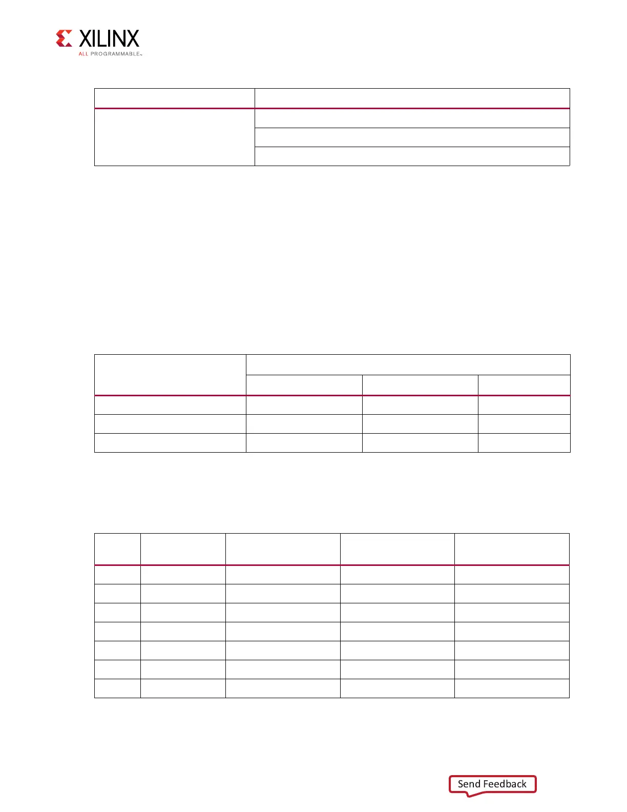
Table 1-16: PHY Default Interface Mode
Mode
Jumper Settings
J29 J30 J64
GMII/MII to copper (default) Jumper over pins 1-2 Jumper over pins 1-2 No jumper
SGMII to copper, no clock Jumper over pins 2-3 Jumper over pins 2-3 No jumper
RGMII Jumper over pins 1-2 No jumper Jumper on
Table 1-17: Board Connections for PHY Configuration Pins
Pin
Connection on
Board
Bit[2] Definition and
Value
Bit[1] Definition and
Value
Bit[0] Definition and
Value
CFG0 V
CC
2.5V PHYADR[2] = 1 PHYADR[1] = 1 PHYADR[0] = 1
CFG1 Ground ENA_PAUSE = 0 PHYADR[4] = 0 PHYADR[3] = 0
CFG2 V
CC
2.5V ANEG[3] = 1 ANEG[2] = 1 ANEG[1] = 1
CFG3 V
CC
2.5V ANEG[0] = 1 ENA_XC = 1 DIS_125 = 1
CFG4 V
CC
2.5V HWCFG_MD[2] = 1 HWCFG_MD[1] = 1 HWCFG_MD[0] = 1
CFG5 V
CC
2.5V DIS_FC = 1 DIS_SLEEP = 1 HWCFG_MD[3] = 1
CFG6 PHY_LED_RX SEL_BDT = 0 INT_POL = 1 75/50Ω= 0
Table 1-15: SFP+ Module Control and Status (Cont’d)
SFP Control/Status Signal Board Connection

 Loading...


