KC705 Evaluation Board 61
UG810 (v1.8) March 20, 2018 www.xilinx.com
Chapter 1: KC705 Evaluation Board Features
CAUTION! Do NOT plug a PC ATX power supply 6-pin connector into J49 on the KC705 board The ATX
6-pin connector has a different pinout than J49. Connecting an ATX 6-pin connector into J49 will
damage the KC705 board and void the board warranty.
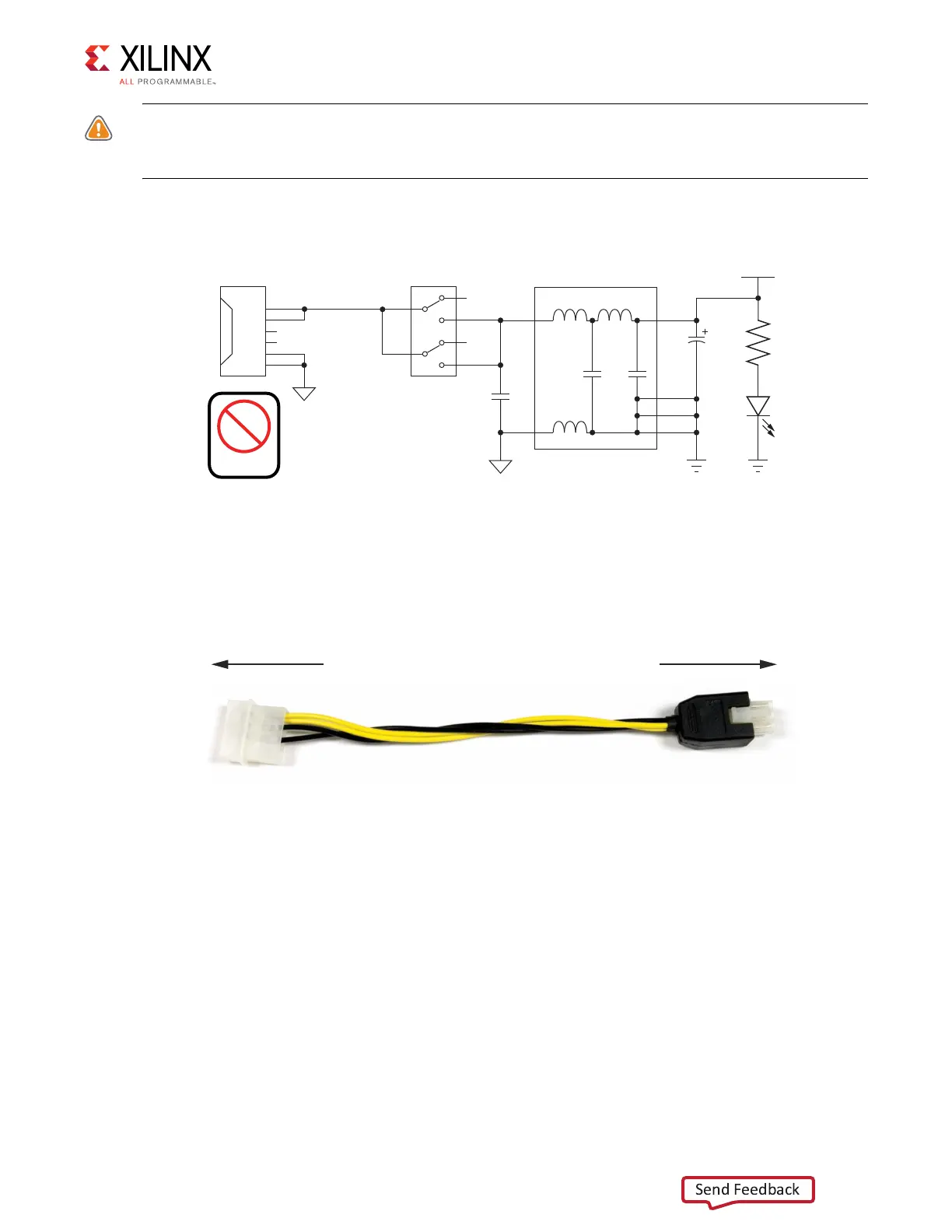
Figure 1-31 shows the power connector J49, power switch SW15 and indicator LED DS22.
The KC705 Evaluation Kit provides the adapter cable shown in Figure 1-32 for powering the
KC705 board from the ATX power supply 4-pin peripheral connector. The Xilinx part number
for this cable is 2600304, and is equivalent to Sourcegate Technologies part number
AZCBL-WH-1109-RA4. For information on ordering this cable, see [Ref 20].
FPGA_PROG_B Pushbutton SW14 (Active-Low)
[Figure 1-2, callout 28]
Switch SW14 grounds the FPGA PROG_B pin when pressed. This action initiates an FPGA
reconfiguration. The FPGA_PROG_B signal is connected to FPGA U1 pin K10.
See 7 Series FPGAs Configuration User Guide (UG470) [Ref 2] for further details on
configuring the 7 series FPGAs.
X-Ref Target - Figure 1-31
Figure 1-31: Power On/Off Switch SW15
X-Ref Target - Figure 1-32
Figure 1-32: ATX Power Supply Adapter Cable
VCC12_P_IN
VCC12_P
R369
1kΩ
1%
INPUT_GND
1
2
3
4
SW15
GND
C539
330μF
25V
C804
1μF
25V
GND
DS22
5
6
J49
1
2
3
4
5
6
12V
N/C
COM
12V
N/C
COM
INPUT_GND
Power
PCIe
U115
1
3
8
7
6
5
UG810_c1_31_031214
UG810_c1_32_031214
To ATX 4-Pin Peripheral
Power Connector
To J49 on KC705 Board

 Loading...


