KC705 Evaluation Board 53
UG810 (v1.8) March 20, 2018 www.xilinx.com
Chapter 1: KC705 Evaluation Board Features
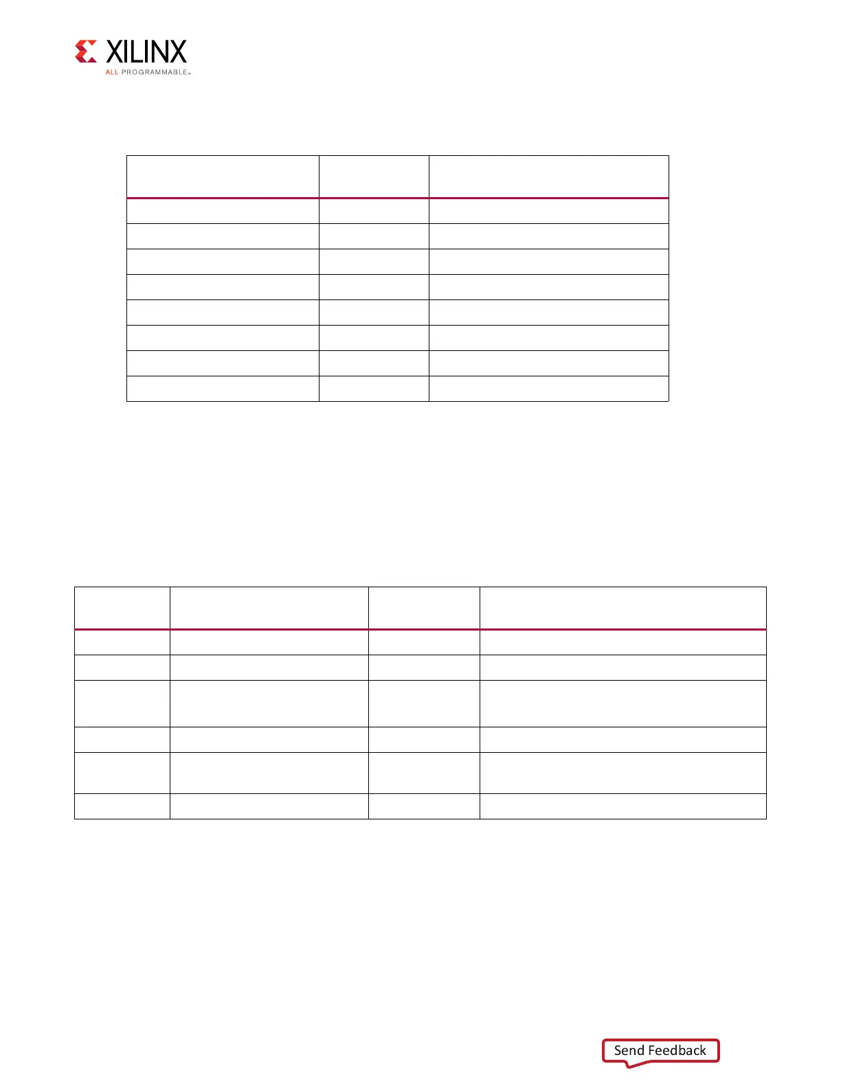
Table 1-24 lists the address for each device on the I2C bus.
For more information about the TI PCA9548 part, see [Ref 19].
Status LEDs
[Figure 1-2, callout 21]
Table 1-25 defines the status LEDs. For user controlled LEDs see User I/O.
Table 1-24: I2C Devices
I2C Device
I2C Switch
Position
I2C Address
Si570 Clock 0 0b1011101
FMC HPC 1 0bXXXXXXX
FMC LPC 2 0bXXXXXXX
IIC EEPROM 3 0b1010100
SFP Module 4 0b1010000
ADV7511 HDMI 5 0b0111001
DDR3 SODIMM 6 0b1010000, 0b0011000
Si5324 Clock 7 0b1101000
Table 1-25: Status LEDs
Reference
Designator
Signal Name Color Description
DS14 PWRCTL1_VCC4A_PG Green FMC power good
DS20 FPGA_DONE Green FPGA configured successfully
DS21 FPGA_INIT_B Green/red GREEN: FPGA initialization successful,
RED: FPGA initialization in progress
DS22 VCC12_P_IN Green 12V power ON
DS23 PWRCTL_PWRGOOD Green UCD9248 power controllers (U55, U56) power
good
DS24 LINEAR_POWER_GOOD Green TPS51200 (U33) VTTDDR Power Good

 Loading...


