KC705 Evaluation Board 60
UG810 (v1.8) March 20, 2018 www.xilinx.com
Chapter 1: KC705 Evaluation Board Features
Switches
[Figure 1-2, callout 27 - 28]
The KC705 evaluation board includes a power and a configuration switch:
• Power on/off slide switch SW15 (callout 27)
• FPGA_PROG_B SW14, active-Low (callout 28)
Power On/Off Slide Switch SW15
[Figure 1-2, callout 27]
The KC705 board power switch is SW15. Sliding the switch actuator from the Off to On
position applies 12V power from J49, a 6-pin mini-fit connector. Green LED DS22
illuminates when the KC705 board power is on. See Power Management for details on the
onboard power system.
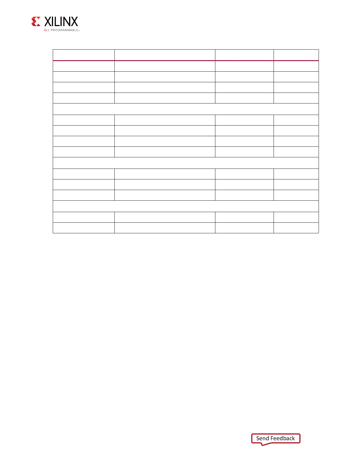
AB12 GPIO_SW_S LVCMOS15 SW4.1
AC6 GPIO_SW_W LVCMOS15 SW6.1
G12 GPIO_SW_C LVCMOS25 SW5.1
AB7 CPU_RESET LVCMOS15 SW7.1
4-Pole DIP Switch
Y29 GPIO_DIP_SW0 LVCMOS25 SW11.4
W29 GPIO_DIP_SW1 LVCMOS25 SW11.3
AA28 GPIO_DIP_SW2 LVCMOS25 SW11.2
Y28 GPIO_DIP_SW3 LVCMOS25 SW11.1
User Rotary Switch
Y25 ROTARY_INCB SW LVCMOS25 SW8.6
AA26 ROTARY_PUSH SW LVCMOS25 SW8.5
Y26 ROTARY_INCA SW LVCMOS25 SW8.1
User SMA
Y23 USER_SMA_GPIO_P LVCMOS25 J13.1
Y24 USER_SMA_GPIO_N LVCMOS25 J14.1
Table 1-27: GPIO Connections to FPGA U1 (Cont’d)
U1 FPGA Pin Schematic Net Name I/O Standard GPIO Pin

 Loading...


