KC705 Evaluation Board 75
UG810 (v1.8) March 20, 2018 www.xilinx.com
Chapter 1: KC705 Evaluation Board Features
Monitoring Voltage and Current
Voltage and current monitoring and control are available for selected power rails through
the Texas Instruments Fusion Digital Power GUI. The three onboard TI power controllers
(U55 at address 52, U56 at address 53, and U89 at address 54) are wired to the same PMBus.
The PMBus connector, J39, is provided for use with the TI USB Interface Adapter PMBus pod
(TI part number EVM USB-TO-GPIO), which can be ordered from the TI website [Ref 23], and
the associated TI Fusion Digital Power Designer GUI (downloadable from [Ref 24]). This is
the simplest and most convenient way to monitor the voltage and current values for the
power rail listed in Table 1-31, Table 1-32 and Table 1-33.
In each of these the three tables (one per controller), the Power Good (PG) On Threshold is
the set-point at or below which the particular rail is deemed “good”. The PG Off Threshold
is the set-point at or below which the particular rail is no longer deemed “good”. The
controller internally ORs these PG conditions together and drives an output PG pin High
only if all active rail PG states are “good”. The On and Off Delay and rise and fall times are
relative to when the board power on-off slide switch SW15 is turned on and off.
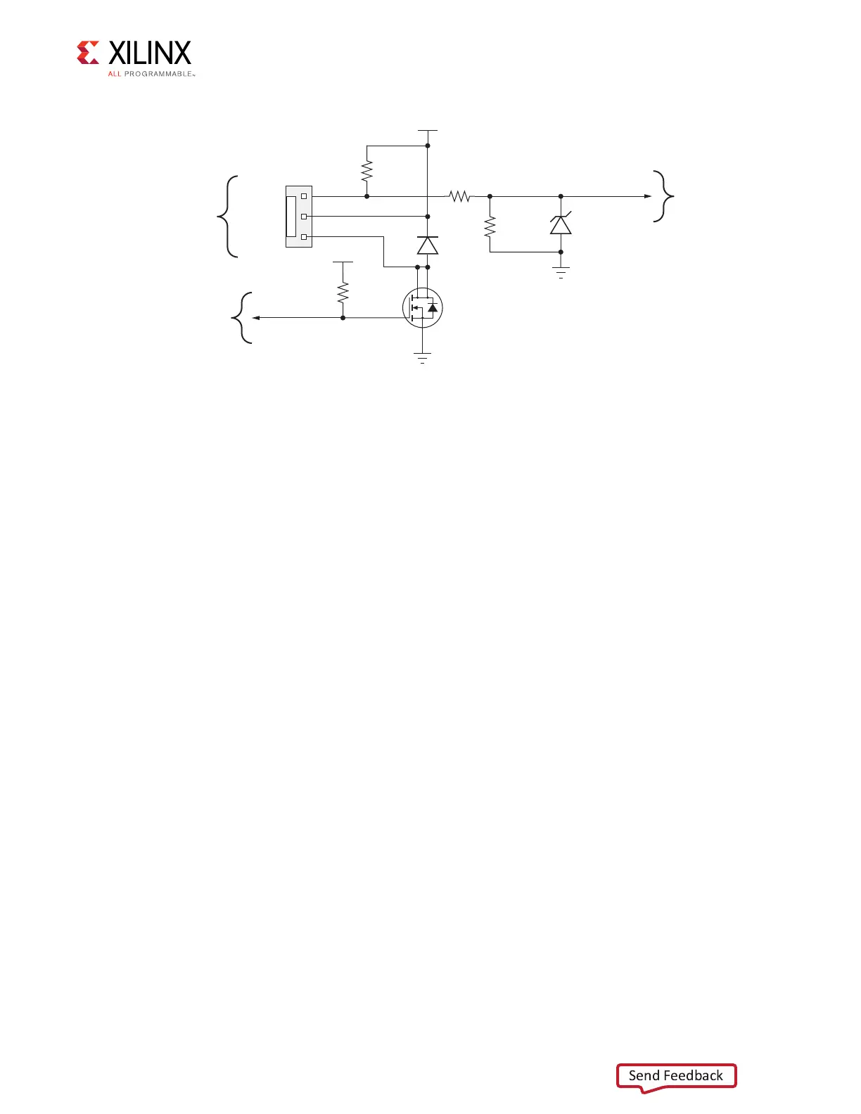
X-Ref Target - Figure 1-36
Figure 1-36: FPGA Cooling Fan Circuit
GND
SM_FAN_PWM
SM_FAN_TACH
1
2
3
J61
R392
10.0K 1%
1/10W
GND
R391
1.00K 1%
1/16W
D15
2.7V
500 mW
MM3Z2V7B
R390
4.75K 1%
1/10W
R393
10.0K 1%
1/10W
VCC12_P
D14
100V
500 mW
DL4148
Q17
NDT30555L
1.3 W
1
2
3
4
VCC2V5
UG810_c1_36_031214
Cooling
Fan
FPGA
U1 Pin L26
FPGA
U1 Pin U22
Fan GND
Fan +12V
Fan Tach

 Loading...


