KC705 Evaluation Board 54
UG810 (v1.8) March 20, 2018 www.xilinx.com
Chapter 1: KC705 Evaluation Board Features
Ethernet PHY Status LEDs
[Figure 1-2, callout 21]
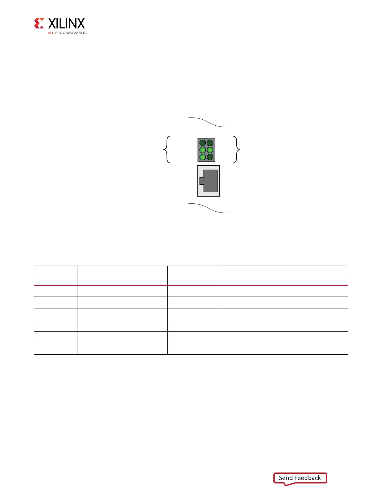
The Ethernet PHY status LEDs are mounted to be visible through the metal bracket on the
left edge of the KC705 board when it is installed into a PCIe slot in a PC chassis. The six PHY
status LEDs are located above the RJ45 Ethernet jack as shown in Figure 1-24.
Table 1-26 lists the Ethernet PHY status LEDs.
User I/O
[Figure 1-2, callout 22 - 26]
The KC705 board provides the following user and general purpose I/O capabilities:
• Eight user LEDs (callout 22)
°
GPIO_LED_[7-0]: DS27, DS26, DS25, DS3, DS10, DS1, DS4
• Five user pushbuttons and reset switch (callout 23)
X-Ref Target - Figure 1-24
Figure 1-24: Ethernet PHY Status LEDs
Direction
Indicator
Link Rate
(Mb/s)
TX 100
RX
Half Duplex 10
1000
RJ45 Ethernet
Jack
UG810_c1_24_031214
Table 1-26: Ethernet PHY Status LEDs
Reference
Designator
Signal Name Color Description
DS11 PHY_LED_RX GREEN Ethernet PHY RX
DS11 PHY_LED_LINK1000 GREEN Ethernet Link Speed is 1000 Mb/s
DS12 PHY_LED_TX GREEN Ethernet PHY TX
DS12 PHY_LED_LINK100 GREEN Ethernet Link Speed is 100 Mb/s
DS13 PHY_LED_DUPLEX GREEN Ethernet Link is Half-duplex
DS13 PHY_LED_LINK10 GREEN Ethernet Link Speed is 10 Mb/s

 Loading...


