KC705 Evaluation Board 46
UG810 (v1.8) March 20, 2018 www.xilinx.com
Chapter 1: KC705 Evaluation Board Features
connector J6). The CP2103GM is powered by the USB 5V provided by the host PC when the
USB cable is plugged into the USB port on the KC705 board.
Xilinx UART IP is expected to be implemented in the FPGA fabric. The FPGA supports the
USB-to-UART bridge using four signal pins: Transmit (TX), Receive (RX), Request to Send
(RTS), and Clear to Send (CTS).
Silicon Labs provides royalty-free Virtual COM Port (VCP) drivers for the host computer.
These drivers permit the CP2103GM USB-to-UART bridge to appear as a COM port to
communications application software (for example, Tera Term or HyperTerm) that runs on
the host computer. The VCP device drivers must be installed on the host PC prior to
establishing communications with the KC705 board.
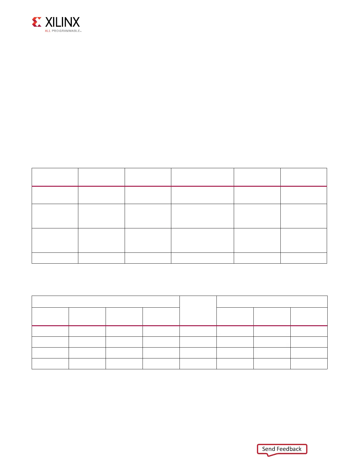
Table 1-19 shows the USB signal definitions at J6.
Table 1-20 shows the USB connections between the FPGA and the UART.
For more information about the CP2103GM and to download the VCP drivers see [Ref 7].
Table 1-19: USB J6 Mini-B Receptacle Pin Assignments and Signal Definitions
USB Receptacle
Pins (J6)
Receptacle Pin
Name
Schematic Net
Name
Description
U12 Pin
(CP2103GM)
U12 Pin Name
(CP2103GM)
1 VBUS USB_VBUS +5V from host system
- U12 CP2103 power
7, 8 REGIN, VBUS
2 D_N USB_D_N Bidirectional
differential serial data
(N-side)
4D-
3 D_P USB_D_P Bidirectional
differential serial data
(P-side)
3D+
4 GND USB_GND Signal ground 2, 29 GND, GND
Table 1-20: FPGA to UART Connections
FPGA U1
Schematic
Net Name
CP2103 Device U12
Pin Function Direction
I/O
Standard
Pin Function Direction
L27 RTS Output LVCMOS25 USB_CTS 22 CTS Input
K23 CTS Input LVCMOS25 USB_RTS 23 RTS Output
K24 TX Output LVCMOS25 USB_RX 24 RXD Input
M19 RX Input LVCMOS25 USB_TX 25 TXD Output

 Loading...


