4
-6
Settings for the Control Methods
Autotuning methods depend on the control method set for the Inverter. Make the settings required by the con-
trol method.
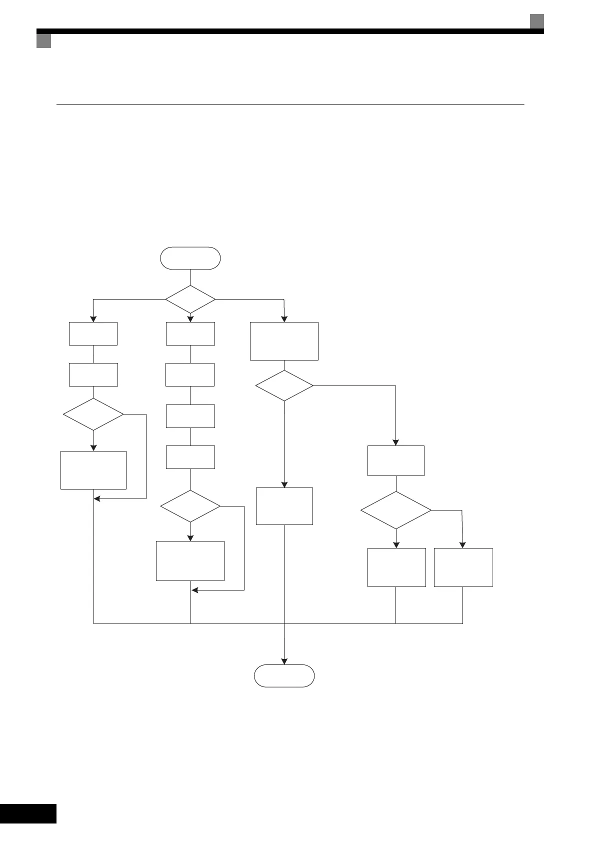
Overview of Settings
Make the required settings in quick programming mode and autotuning mode according to the following flow-
chart.
Note 1. Autotuning is not necessary if the motor constants are already known from a motor test report. Set the E2 motor constants to the test report values
(refer to page 6-119). However, if the length of the motor cable exceeds 50 m, perform autotuning.
2. If the motor cable changes to 50 m or longer for the actual installation, perform stationary autotuning for the line-to-line resistance only on-site.
* 1. Use rotational autotuning to increase autotuning accuracy whenever it is okay for the motor to be operated. Always perform rotational autotuning when
using open-loop vector 2 control.
* 2. If there is a reduction gear between the motor and PG, set the reduction ratio in F1-12 and F1-13.
* 3. The default setting of the Inverter is for open-loop vector 1 control (A1-02 = 2).
* 4. If the maximum output frequency is different from the base frequency, set the maximum output frequency (E1-04) after autotuning.
Fig 4.3 Settings According to the Control Method
50 m or longer
Yes
50 m or longer
Less than 50 m
START
END
No
Exceeds 30%
Within 30%
Less than 50 m
V/f control
(A1-02 = 0)
V/f control with PG
(A1-02 = 1)
Vector control
(A1-02 = 2,3,4)
*1
*3
V/f control
Set A1-02 to 0.
Set V/f pattern
in E1.
Cable
between Inverter
and motor over
50 m?
Control
method (A1-02)?
Autotuning
T1-01 = 2
Perform stationary
autotuning for the
line-to-line resistance only.
V/f control with
PG
Set A1-02 to 1.
Set number of
motor poles in
E2-04.
Set PG constant
in F1-01.
*2
Cable
between Inverter
and motor over
50 m?
Autotuning
T1-01 = 2
Perform stationary
autotuning for the line-to-line
resistance only.
Open-loop vector 1 control
A1-02 = 2
Flux vector control
A1-02 = 3
Open-loop vector 2 control
A1-02 = 4
Can
motor and load
be separated?
Autotuning
*4
T1-01 = 0
Perform rotational
autotuning.
Autotuning
Perform stationary
autotuning.
Motor-load ratio
during initial operation
after tuning within
30%?
Autotuning
*4
T1-01 = 1
Perform stationary
autotuning 1.
Autotuning
*4
T1-01 = 4
Perform stationary
autotuning 2.
Set V/f pattern
in E1.
When using open-loop vector 2 control,
precision settings for control constants
are required after the motor constant
have been set.
(Refer to page 6-122.)
(Refer to page 6-122.)
(Refer to page 6-119.)
(Refer to page 4-16.)
(Refer to page 4-10.)
(Refer to page 4-13.)
(Refer to page 4-19.)
(Refer to page 4-16.)
TOE-S616-60.1.book 6 ページ 2017年8月4日 金曜日 午後3時41分
 Loading...


