Wiring Control Circuit Terminals
2-
35
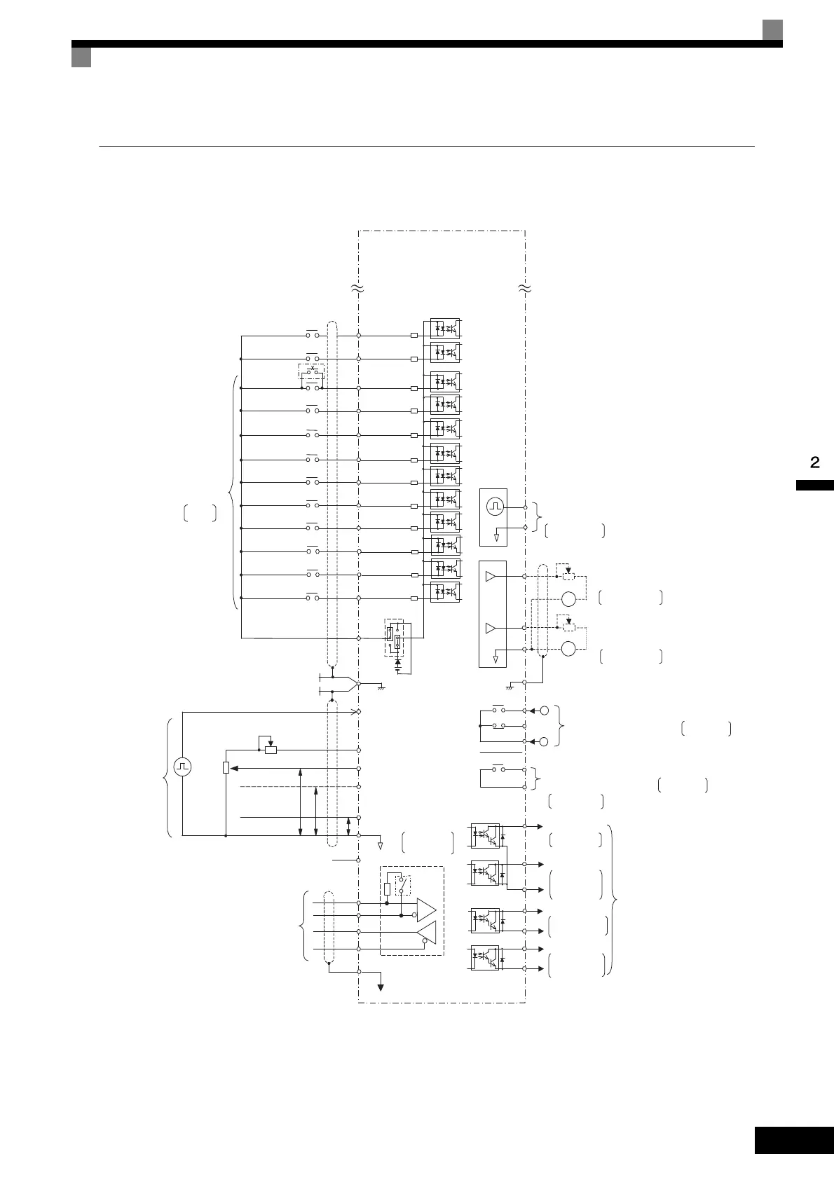
Control Circuit Terminal Connections
Connections to Inverter control circuit terminals are shown in Fig 2.19.
Fig 2.19 Control Circuit Terminal Connections
Inverter
CIMR-G7A2018
P2
PC
Open collector 1
Open collector 2
Multi-function
open-collector outputs
48 VDC, 50 mA
P1
Default:
Frequency
agree signal
Default: Zero
speed
MA
MB
MC
Error contact output
250 VAC, 10 mA min. 1 A max.
30 VDC, 10 mA min. 1 A max.
M1
M2
Multi-function contact output
250 VAC, 10 mA min. 1 A max.
30 DC, 10 mA min. 1 A max.
Default: Running
signal
AC
MP
Pulse train output
Default: Output
frequency
S5
S8
S9
Multi-step speed
setting 3
Multi-step speed
setting 4
S1
S2
S3
S4
Forward Run/Stop
Reverse Run/Stop
External fault
Fault reset
Multi-function
contact input
Defaults
IG
MEMOBUS
communications
RS-485/422
R-
R+
S-
S+
Terminating
resistance
FM
AM
Multi-function analog output 1
AC
E(G)
-10 to 10 V 2 mA
AM
FM
+
+−
−
Default: Output current
0 to +10 V
Default: Output current
0 to +10 V
-10 to 10 V 2 mA
Multi-function analog output 2
Ammeter adjustment
20 kΩ
Ammeter adjustment
20 kΩ
+24V 8mA
SC
+24V
CN5 (NPN setting)
P4
C4
P3
S6
S7
Multi-step speed
setting 2
Jog frequency
selection
S11
S12
S10
P
P
4 to 20 mA
0 to 10 V
Pulse train input
RP
+V
A1
A2
AC
0V
Master speed pulse train
Frequency setting power
+15 V 20 mA
Master speed reference
0 to 10 V (20 kΩ)
Master speed reference
4 to 20 mA (250 Ω)
[0 to 10 V (20 kΩ) input]
Frequency setting
adjustment
Frequency
setter
2 kΩ
External
frequency
references
2 kΩ
2
1
3
E(G)
A3
0 to 10 V
P
-V
(−15V 20mA)
C3
MA
MC
43
0 to 32 kHz (3 kΩ)
High level: 3.5 to 13.2 V
input
0 to 32 kHz (2.2 kΩ)
Multi-step command 1
(Main speed switching)
External
baseblock command
for Braking Unit
Thermal switch contact
Acc/dec time 1
Emergency stop (NO)
Shield wire
connection terminal
Multi-function anlog input
0 to 10 V
(20 kΩ)
Factory setting:
Auxiliary frequency
reference
Open collector 3
Open collector 4
Factory setting:
Minor fault
Factory setting:
Inverter operation
ready
Min. load
5 VDC, 10 mA
Min. load
5 VDC, 10 mA
TOE-S616-60.1.book 35 ページ 2017年8月4日 金曜日 午後3時41分
 Loading...


