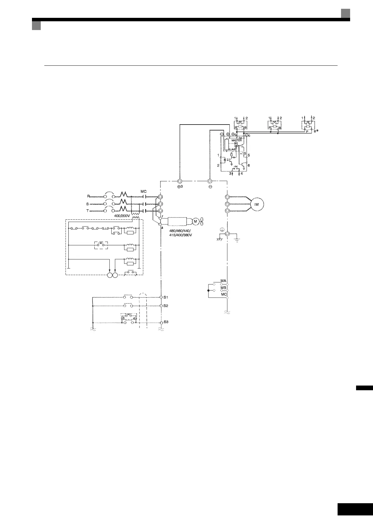
EasyManuals Logo
Home>YASKAWA>Inverter>Varispeed G7 Series

YASKAWA Varispeed G7 Series User Manual

YASKAWA Varispeed G7 Series
541 pages
To Next Page IconTo Next Page
To Previous Page IconTo Previous Page
Page #515 background imageLoading...
Page #515 background image
Wiring Examples
10-
27
10
Using a Braking Unit and Three Braking Resistor Units in Parallel
This example shows wiring for using three Braking Resistor Units in parallel.
Fig 10.16
THRX
THRX
12
TRX
TRX
MBMC
2MCCB
MA MC
OFF
ON
MC
MC
SA
SA
SA
Braking Resistor Unit
thermal relay trip contacts
Fault contacts
Thermal
protector
Thermal
protector
Thermal
protector
Braking
Resistor
Unit
Braking
Resistor
Unit
Braking
Resistor
Unit
Braking Unit
Thermal switch
Inverter
Motor
Cooling fan
Ground Fault Interrupter or Molded-case Circuit Breaker
3-phase power
supply, 380 to
480 V at 50/60 Hz
Voltage
setting
Ground to 10 Ω max.
Fault contact outputs
Forward Run Com-
mand (forward run
when ON)
Reverse Run Com-
mand (reverse run
when ON)
Forward Run/Stop
Reverse Run/Stop
Braking Unit
External fault
* Disable the stall prevention during deceleration (set constant L3-04 to 0) when using a Brak-
ing Resistor Unit. If this user constant is not changed to disable stall prevention, the system
may not stop in the set deceleration time.
Level
detector
A sequence is required to turn OFF the
power supply for the thermal protector trip
contacts of the Braking Resistor Unit.
R/L1
S/L2
T/L3
U/T1
V/T2
W/T3
TOE-S616-60.1.book 27 ージ 017年8月4日 金曜日 午後3時41

Table of Contents

Questions and Answers:

Question and Answer IconNeed help?

Do you have a question about the YASKAWA Varispeed G7 Series and is the answer not in the manual?

YASKAWA Varispeed G7 Series Specifications

General IconGeneral
BrandYASKAWA
ModelVarispeed G7 Series
CategoryInverter
LanguageEnglish

Related product manuals