5
-74
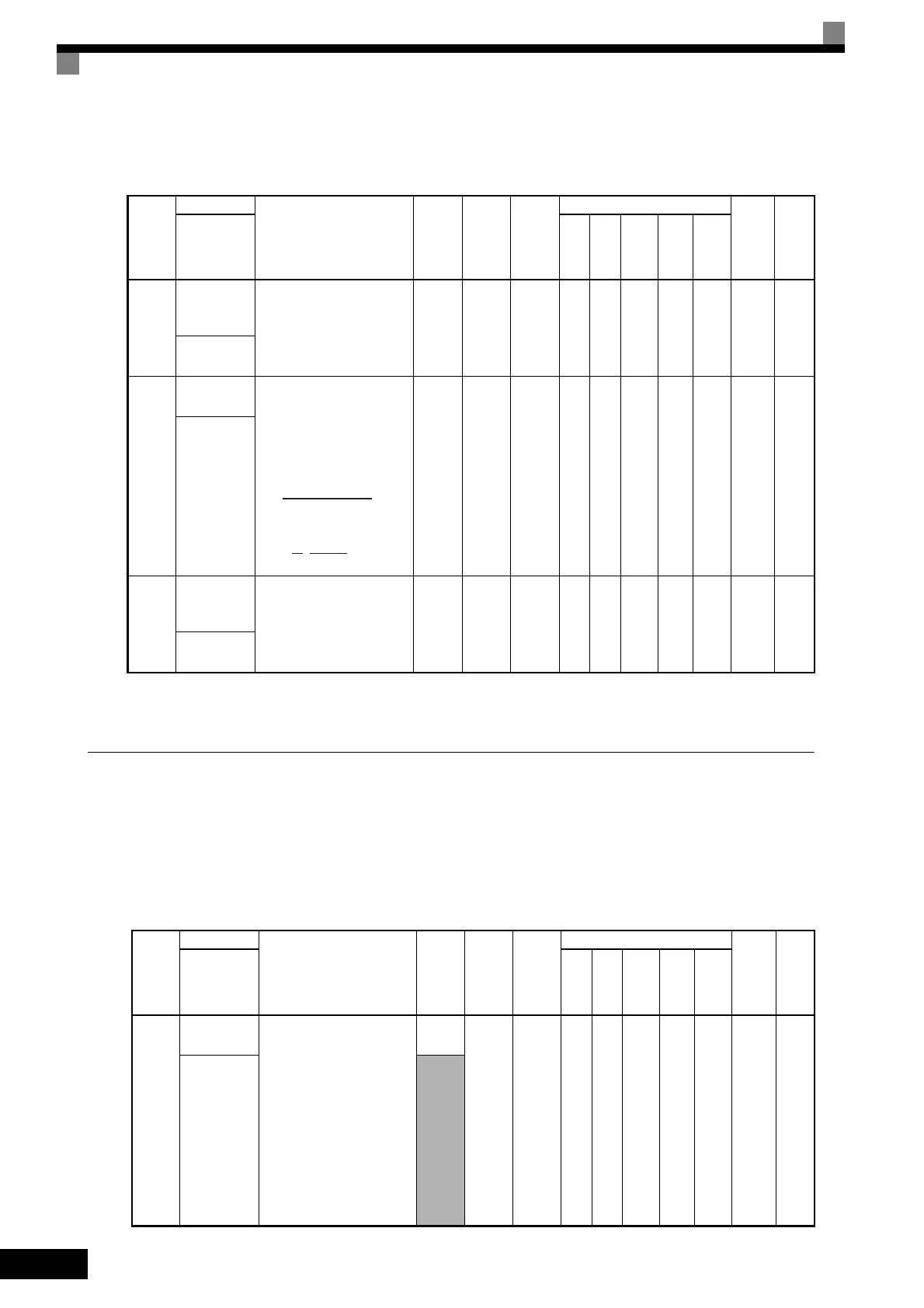
Feed Forward: N5
User constants for the feed forward control are shown in the following table.
* 1. When the control method is changed, the factory setting will change. The flux vector factory setting is given.
* 2. The factory setting depends on the Inverter capacity. The value for a 200 V Class Inverter of 0.4 kW is given.
o: Digital Operator Constants
The following settings are made with the Digital Operator constants (o constants): Multi-function selections
and the copy function.
Monitor Select: o1
User constants for Digital Operator Displays are shown in the following table.
Con-
stant
Number
Name
Description
Setting
Range
Factory
Setting
Change
during
Opera-
tion
Control Methods
MEMO-
BUS
Regis-
ter
Page
Display
V/f
V/f
with
PG
Open
Loop
Vec-
tor
1
Flux
Vec-
tor
Open
Loop
Vec-
tor
2
N5-01
Feed forward
control
selection
Select the feed forward con-
trol.
0: Disabled
1: Enabled
0 or 1
0
*1
No No No No A A 5B0H
4-33
6-144
Feedfoward
Sel
N5-02
Motor accel-
eration time
Set the time required to
accelerate the motor at the
rated torque (T
100
) to the
rated speed (Nr).
J: GD
2
/4, P: Motor rated out-
put
However,
0.001
to
10.000
0.178 s
*2
No No No No A A 5B1H
4-33
6-144
Motor Accel
Time
N5-03
Feed forward
proportional
gain
Set the proportional gain for
feed forward control.
Speed reference response will
increase as the setting of N5-
03 is increased.
0.00 to
100.00
1.0 No No No No A A 5B2H
4-33
6-144
Feedfoward
Gain
Con-
stant
Number
Name
Description
Setting
Range
Fac-
tory
Setting
Change
during
Opera-
tion
Control Methods
MEMO-
BUS
Regis-
ter
Page
Display
V/f
V/f
with
PG
Open
Loop
Vec-
tor
1
Flux
Vec-
tor
Open
Loop
Vec-
tor
2
o1-01
Monitor
selection
Select the number of the
monitor item to display
fourth in drive mode (the
numeric value in the
portion of U1-).
The output monitor voltage
(factory setting) can be
changed.
If o1-02 is set to 4 when
using the Digital Operator
(LCD), the monitor item set
in o1-01 when the power sup-
ply is turned ON is displayed.
4 to 45
6 YesAAAAA500H–
User Moni-
tor Sel
4 to 99
2π J [kgm
2
] Nr [min
-1
]
ta =
60
T
100
[N m]
[s]
T
100
=
× 10
3
[N m]
60
2π
P [kW]
Nr [min
-1
]
TOE-S616-60.1.book 74 ページ 2017年8月4日 金曜日 午後3時41分
 Loading...


