Precautions when Using Peripheral Devices
2-
7
Power Factor Improvement (Elimination of Phase-advancing Capacitors)
Install a DC reactor or an AC reactor on the power supply side of the Inverter to improve the power factor.
(DC reactors are built into 200 V Class models for 18.5 to 110 kW and 400 V Class models for 18.5 to 300
kW.)
The capacitor to improve the power factor and the surge absorber on the Inverter output side may overheat or
become damaged due to the harmonic components of Inverter output. Do not use a capacitor or surge absorber
because overcurrent will flow to the Inverter and trigger overcurrent protection.
Radio Wave Interference
The Inverter’s main circuit input and output contain harmonic components, and these may interfere with com-
munications devices (AM radios, for example) that are used near the Inverter. The interference can be reduced
by installing a noise filter. Placing the power supply-side wiring between the Inverter and the motor in a metal
pipe and grounding the metal pipe is also effective.
Wire Thickness and Wiring Distance
If the length of the wiring between the Inverter and the motor is long (particularly during low-frequency out-
put), the torque of the motor will decrease due to the voltage drop along the cable. Wire the Inverter and motor
with a cable that has a sufficiently thick wire.
When the Digital Operator is installed away from the Inverter, always use the Digital Operator Connection
Cable (optional). For remote operation with analog signals, keep the control line length between the Digital
Operator or operation signals and the Inverter to 50 m or less, and separate the lines from high-power lines
(main circuits or relay sequence circuits) to reduce induction from peripheral devices. When setting frequen-
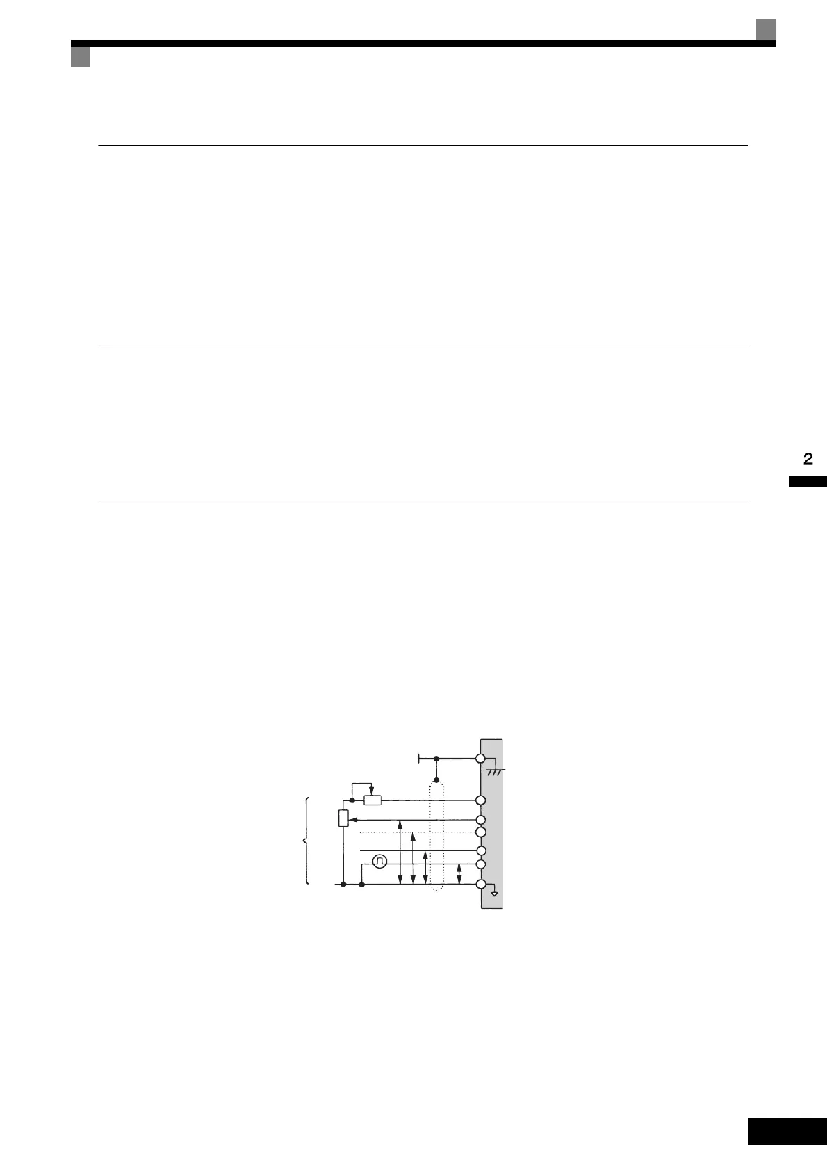
cies from an external frequency setter (and not from a Digital Operator), use a shielded twisted-pair cable and
ground the shield to terminal E (and not the ground), as shown in the following diagram.
Fig 2.1 External Frequency Reference Wiring
External frequency
references
2 kΩ
2 kΩ
0 to 10 V
0 to 10 V
4 to 20 mA
P
P
P
P
0 V
0 V
AC
RP
A2
A3
A1
+V
Shield terminalE (G)
Speed setting power supply
+15 V 20 mA
Master speed reference
0 to 10 V (20 kΩ)
Master speed reference
4 to 20 mA (250 Ω) or
0 to 10 V (20 kΩ)
Multi-function analog input
0 to 10 V (20 kΩ)
TOE-S616-60.1.book 7 ページ 2017年8月4日 金曜日 午後3時41分
 Loading...


