10
-32
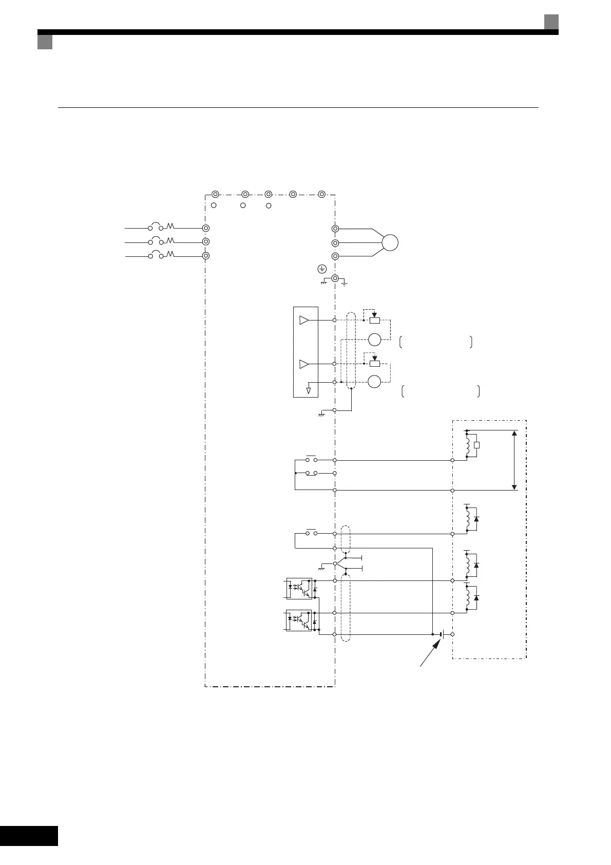
Using Contact and Open Collector Outputs
This example shows wiring for contact outputs and open collector outputs.
The following example is for the CIMR-G7A25P5 (200 V Class Inverter for 5.5 kW).
Fig 10.21
Multi-function
open collector output
48 VDC 50 mA max.
Multi-function contact output
3-phase power
Multi-function analog output 1
㸩
㸩
Default: Output frequency,
0 to +10 V
Default: Ouput current,
0 to +10 V
Multi-function analog output 2
Frequency meter scale adjustment resistor
20 k Ȑ
Ammeter scale adjustment resistor
20 k Ȑ
Sequence external power
supply
30 VDC max.
Flywheel
diode
Sequence
(Default: Freq agree)
250 VAC, 10 mA min. 1 A max.
30 VDC, 10 mA min. 1 A max.
250 VAC, 10 mA min. 1 A max.
30 VDC, 10 mA min. 1 A max.
Flywheel
diode
Flywheel
diode
Open collector 2
Ground Fault Interrupter or
Molded-case Circuit Breaker
TOE-S616-60.1.book 32 ページ 2017年8月4日 金曜日 午後3時41分
 Loading...


