Machine Protection
6-
51
Changing Stall Prevention Level during Operation Using an Analog Input
If you set H3-09 (Multi-function Analog Input Terminal A2 Function Selection) or H3-05 (Multi-function
Analog Input Terminal A3 Function Selection) to 8 (stall prevention level during run), you can change the stall
level during operation by setting H3-10 (Gain (Terminal A2)) and H3-11 (Bias (Terminal A2)) or H3-06 (Gain
(Terminal A3)) and H3-07 (Bias (Terminal A3).
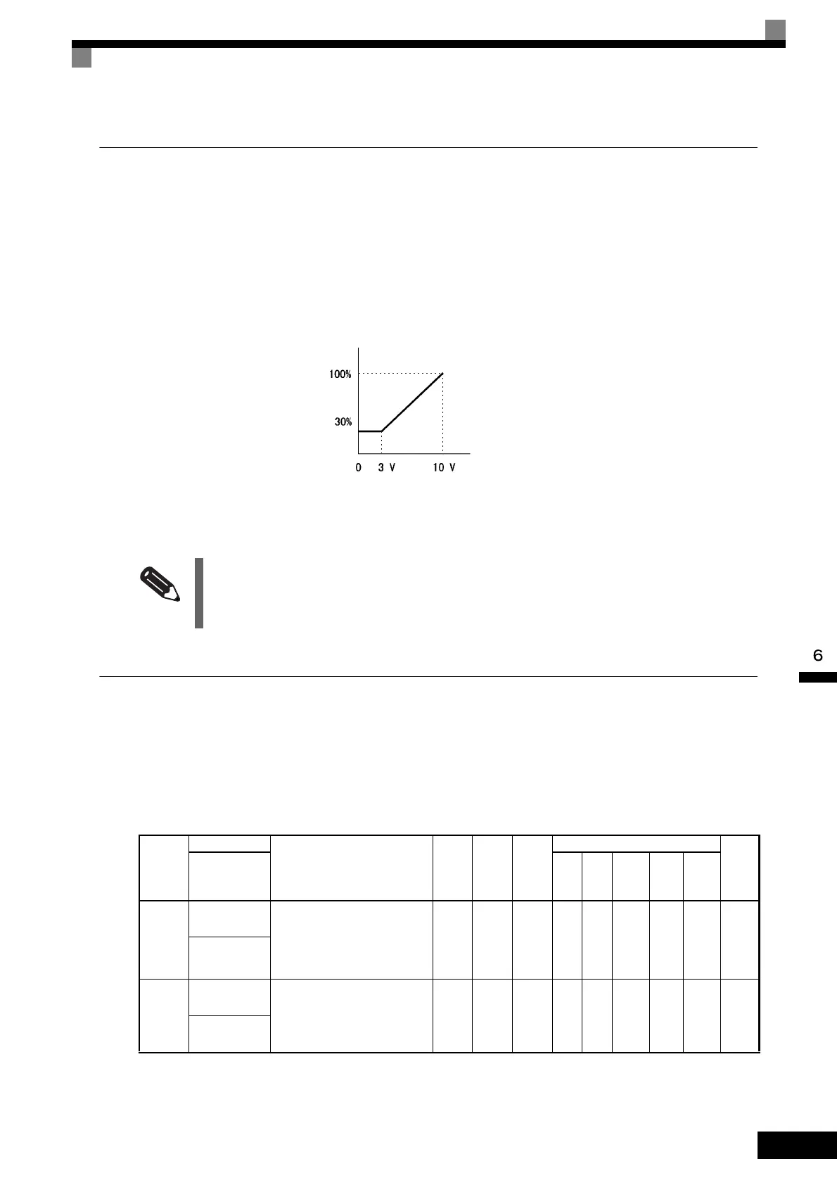
The stall prevention level during operation enabled is the multi-function analog input terminal A2 or A3 input
level or the set value in constant L3-06, whichever is the smaller.
Fig 6.40 Stall Prevention Level during Operation Using an Analog Input
Using Frequency Detection: L4-01 to L4-05
Set these constants when outputting one of the frequency agree or frequency detection signals from a multi-
function output. When using flux vector control, the frequency is detected using the motor speed. When using
open-loop vector 2 control, the frequency is detected using the estimated speed of the motor.
Related Constants
If the motor capacity is smaller than the Inverter capacity or the motor stalls when operating at the factory set-
tings, lower the stall prevention level during operation.
Con-
stant
Number
Name
Description
Setting
Range
Factory
Setting
Change
during
Opera-
tion
Control Methods
MEMO
BUS
Regis-
ter
Display
V/f
V/f
with
PG
Open
Loop
Vector
1
Flux
Vec-
tor
Open
Loop
Vector
2
L4-01
Speed agree
detection level
Set the speed that you want to
detect in Hz.
The set speed is an absolute value,
so the speed is detected in forward
or reverse.
0.0 to
400.0
0.0 Hz No A A A A A 499H
Spd Agree
Level
L4-02
Speed agree
detection width
Set the speed detection range in
Hz.
0.0 to
20.0
2.0 Hz No A A A A A 49AH
Spd Agree
Width
Stall prevention level during operation
Multi-function analog input
terminal A2, A3 input level
(4 mA) (8.8 mA) (20 mA)
TOE-S616-60.1.book 51 ページ 2017年8月4日 金曜日 午後3時41分
 Loading...


