Wiring Main Circuit Terminals
2-
19
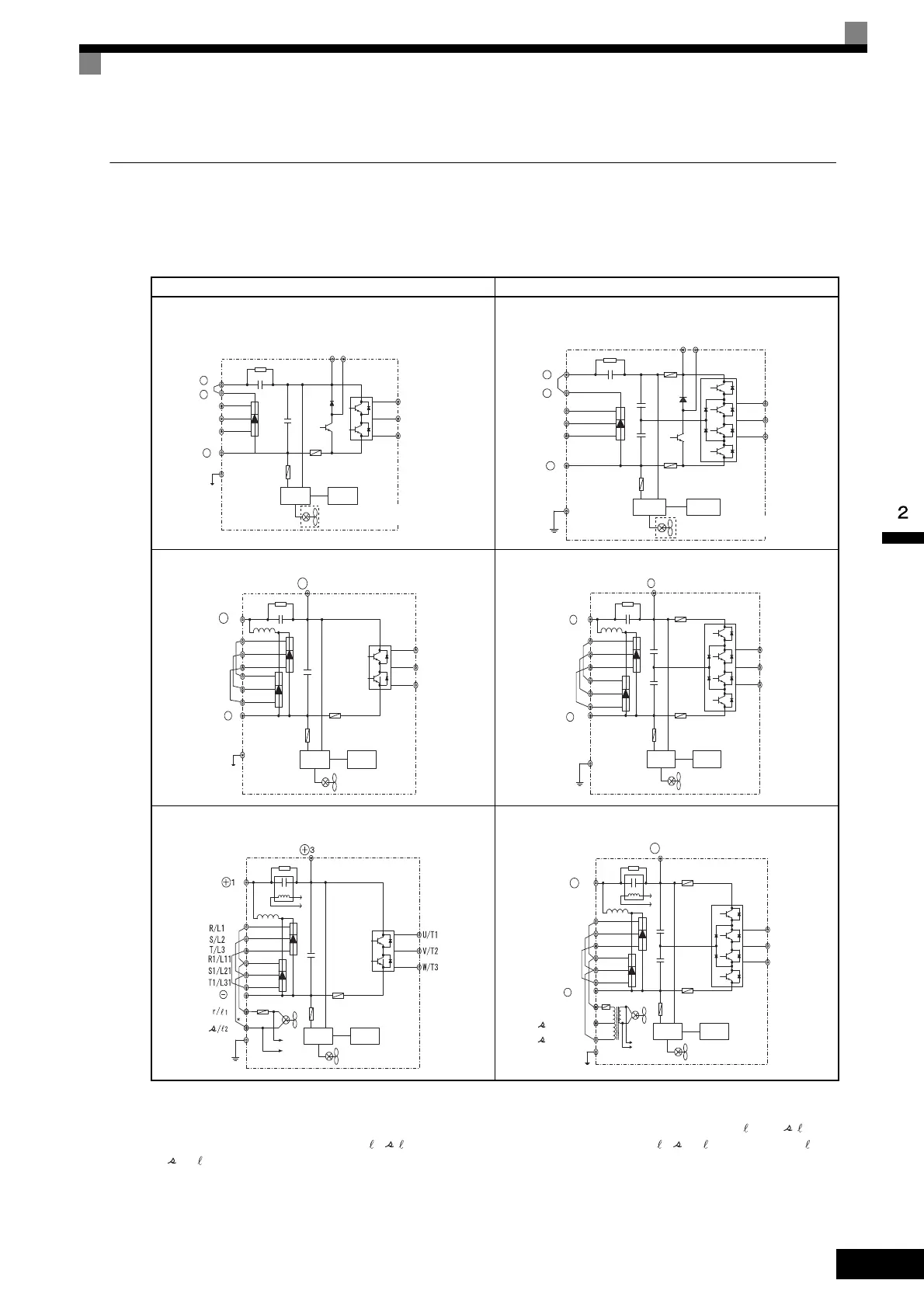
Main Circuit Configurations
The main circuit configurations of the Inverter are shown in Fig 2.5.
Table 2.5 Inverter Main Circuit Configurations
Note 1. Consult your Yaskawa representative before using 12-phase rectification.
Note 2. When installing a molded-case circuit breaker (MCCB) on the DC power supply side, do not use it to turn the Inverter power supply ON and OFF.
* These terminals are wired before shipment. When using DC power for the main circuit power supply, remove the wires between R-r/
1
and S- /
2
, then,
for 200 V Class Inverters, input 200 VAC to r/
1
- /
2
, or, for 400 V Class Inverters, input either 200 VAC to r/
1
- 200/
2
200 or 400 VAC to r/
1
-
400/
2
400.
200 V Class 400 V Class
B1 B2
1
+
+
2
−
Power
supply
Control
circuits
Cooling fan is provided for
Inverters of 2.2 kW or more.
U/T1
V/T2
W/T3
R/L1
S/L2
T/L3
U/T1
V/T2
W/T3
1
+
+
2
R/L1
S/L2
T/L3
Power
supply
Control
circuits
−
B1 B2
Cooling fan is provided for
Inverters of 1.5 kW or more.
+
1
R/L1
S/L2
T/L3
R1/L11
S1/L21
T1/L31
−
+
3
U/T1
V/T2
W/T3
Power
supply
Control
circuits
U/T1
V/T2
W/T3
1
R/L1
S/L2
T/L3
R1/L11
S1/L21
T1/L31
−
3
+
+
Power
supply
Control
circuits
a
Power
supply
Control
circuits
b
a
b
+
1
+
3
200/
2
200
l
400/
2
400
l
R/L1
S/L2
T/L3
R1/L11
S1/L21
T1/L31
U/T1
V/T2
W/T3
−
r/
1
l
*
a
b
a
b
Power
supply
Control
circuits
TOE-S616-60.1.book 19 ページ 2017年8月4日 金曜日 午後3時41分
 Loading...


