Output Terminal Functions
6-
87
Output Terminal Functions
The output terminal function, which sets the output methods by switching the functions of the multi-func-
tion output terminals (M1-M2, P1-PC, P2-PC, P3-C3, and P4-C4), is described here.
During Run (Setting: 0)
During Run 2 (Setting: 37)
• These outputs can be used to indicate the Inverter's operating status.
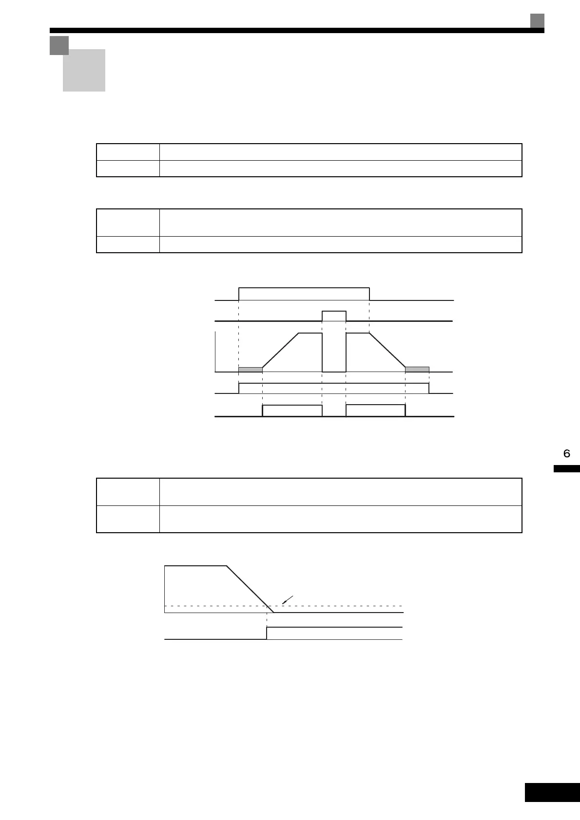
Fig 6.56 Timing Chart for “During RUN” Output
Zero-speed (Setting: 1)
Fig 6.57 Timing Chart for Zero-speed
OFF The Run Command is OFF and there is not output voltage.
ON The Run Command is ON or a voltage is being output.
OFF
The Inverter is not outputting a frequency. (Baseblock, DC injection braking, initial excitation, or
stopped)
ON The Inverter is outputting a frequency.
OFF
The output frequency is greater than the minimum output frequency (E1-09).
(With flux vector control, is greater than the zero-speed level (b2-01).)
ON
The output frequency is less than the minimum output frequency (E1-09).
(With flux vector control, is less than the zero-speed level (b2-01).)
ON
ON
OFF
OFF
ONOFF
ON
Run Command
Baseblock command
Output frequency
During run 1 output
During run 2 output
OFF
OFF
Output frequency
Zero-speed output
ON
Minimum output frequency (E1-09)
(Zero speed level (b2-01) when flux vector control is
being used.)
TOE-S616-60.1.book 87 ページ 2017年8月4日 金曜日 午後3時41分
 Loading...


