Wiring Examples
10-
25
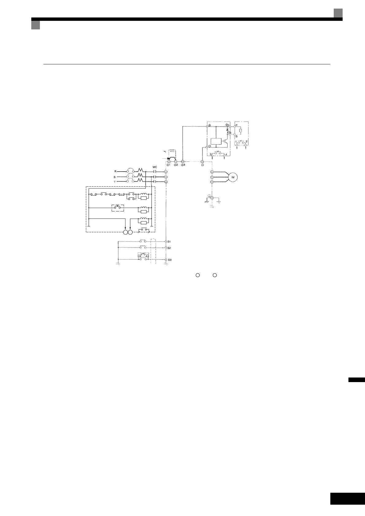
Using a Braking Unit and Braking Resistor Unit
When using a Braking Unit and Braking Resistor Unit, create a sequence to detect overheating of the braking
resistor and cut off the power supply to the Inverter.
CIMR-G7A2018, -G7A2022 (200 V Class Inverters of 18.5 kW, 22 kW)
* 1. Remove the short-circuit bar (standard equipment) from between 1 and 2 before you connect a DC Reactor (optional).
* 2. Disable the stall prevention during deceleration (set constant L3-04 to 0) when using a Braking Resistor Unit. If this user constant is not
changed to disable stall prevention, the system may not stop in the set deceleration time.
Fig 10.14
THRX
THRX
12
TRX
TRX
MBMC
2MCCB
MA MC
OFF
ON
MC
MC
SA
SA
SA
Fault contacts
Braking Resistor Unit
(overheat contacts)
3-phase power supply,
200 to 240 V
at 50/60 Hz
A sequence is required to turn
OFF the power supply for the
thermal protector trip contacts of
the Braking Resistor Unit.
DC Reactor to
improve input
power factor
(Optional)
Short-circuit bar
Ground Fault Interrupter or Molded-case Circuit Breaker
Braking Unit
(Optional)
Inverter
Motor
Level
detector
Braking Resistor Unit
*2
(Optional)
Braking Resistor overheating contacts
(Thermal protector trip contacts)
Ground to 100 Ω max.
Forward Run/Stop
Reverse Run/Stop
Braking Unit
External fault
Forward Run Command (forward run when ON)
Reverse Run Command (reverse run when ON)
R/L1
S/L2
T/L3
U/T1
V/T2
W/T3
Forward Run/Stop
TOE-S616-60.1.book 25 ページ 2017年8月4日 金曜日 午後3時41分
 Loading...


