Trial Operation Procedures
4-
7
Basic Settings
Switch to the quick programming mode (“QUICK” will be displayed on the LCD screen) and then set the fol-
lowing user constants. Refer to Chapter 3 Digital Operator and Modes for Digital Operator operating proce-
dures and to Chapter 5 User Constants and Chapter 6 Constant Settings by Function for details on the user
constants.
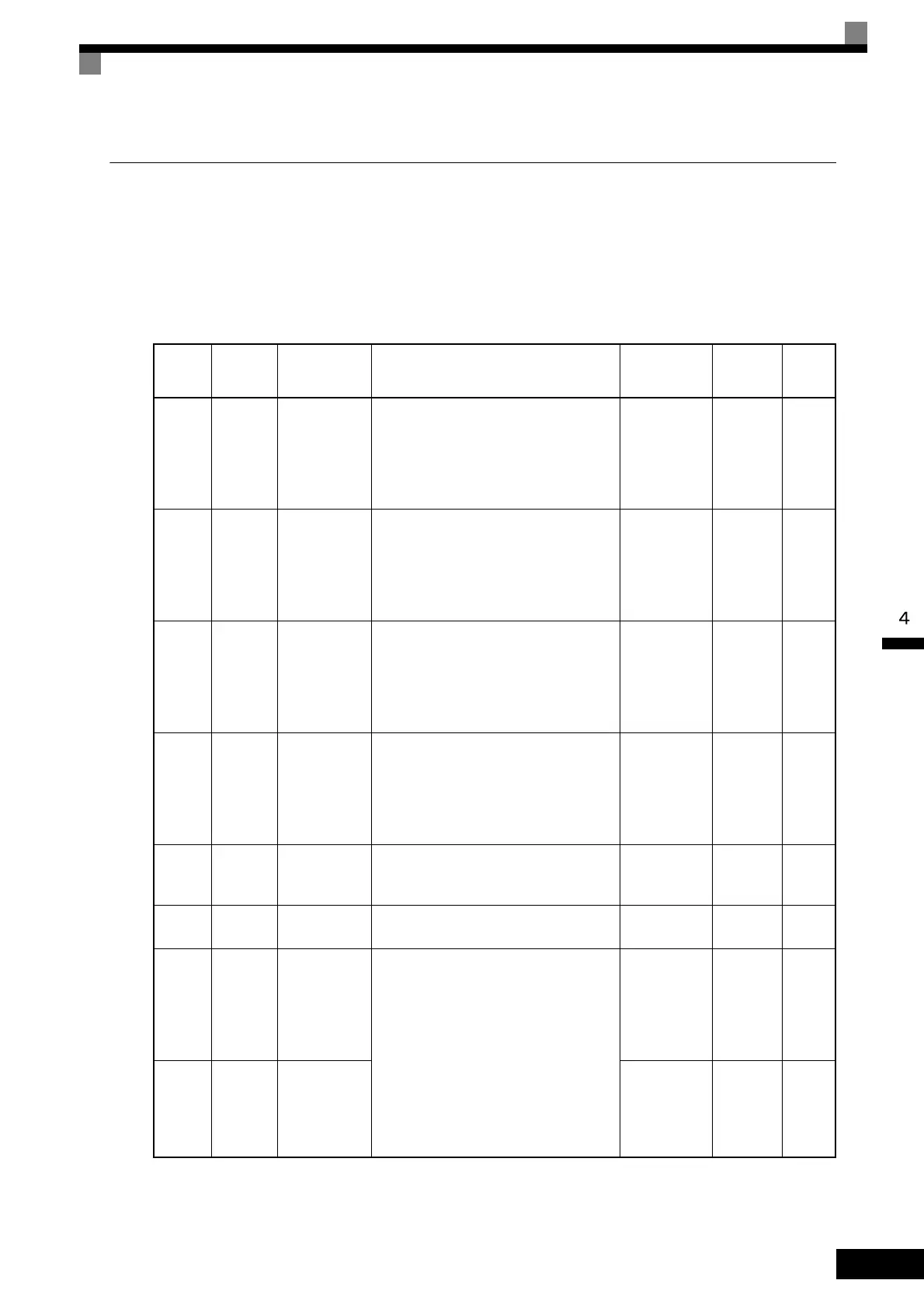
Table 4.1 Basic User Constant Settings
: User constants that must be set, : User constants to be set as necessary.
Cate-
gory
Con-
stant
Number
Name Description
Setting
Range
Factory
Setting
Page
A1-02
Control
method selec-
tion
Set the control method for the Inverter.
0: V/f control
1: V/f control with PG
2: Open-loop vector 1 control
3: Flux vector
4: Open-loop vector 2 control
0 to 4 2 5-9
b1-01
Reference
selection
Set the frequency reference input method.
0: Digital Operator
1: Control circuit terminal (analog input)
2: MEMOBUS communications
3: Option board
4: Pulse train input
0 to 4 1
5-11
6-2
6-77
6-95
b1-02
Operation
method selec-
tion
Set the Run Command input method.
0: Digital Operator
1: Control circuit terminal (sequence
input)
2: MEMOBUS communications
3: Option board
0 to 3 1
5-11
6-10
6-77
6-95
b1-03
Stopping
method selec-
tion
Select stopping method when Stop Com-
mand is sent.
0: Deceleration to stop
1: Coast to stop
2: DC braking stop
3: Coast to stop with timer
0 to 3 0
5-11
6-12
C1-01
Acceleration
time 1
Set the acceleration time in seconds for the
output frequency to climb from 0% to
100%.
0.0 to 6000.0 10.0 s
5-22
6-18
C1-02
Deceleration
time 1
Set the deceleration time in seconds for the
output frequency to fall from 100% to 0%.
0.0 to 6000.0 10.0 s
5-22
6-18
C6-02
Carrier fre-
quency selec-
tion
The carrier frequency is set low if the
motor cable is 50 m or longer or to reduce
radio noise or leakage current.
1 to F
Depends
on capac-
ity, volt-
age, and
control
method.
5-27
C6-11
Carr
ier fre-
quen
cy selec-
tion for open-
loop vector 2
control
1 to 4
1
*
5-27
TOE-S616-60.1.book 7 ページ 2017年8月4日 金曜日 午後3時41分
 Loading...


