7
-2
Protective and Diagnostic Functions
This section describes the alarm functions of the Inverter. The alarm functions include fault detection,
alarm detection, operation error detection, and autotuning error detection.
Fault Detection
When the Inverter detects a fault, the fault contact output operates, and the Inverter output is shut OFF causing
the motor to coast to a stop. (The stopping method can be selected for some faults, and the selected stopping
method will be used with these faults.) A fault code is displayed on the Digital Operator.
When a fault has occurred, refer to the following table to identify and correct the cause of the fault.
Use one of the following methods to reset the fault before restarting the Inverter:
• Set a multi-function contact input (H1-01 to H1-05) to 14 (Fault Reset) and turn ON the fault reset signal.
• Press the RESET Key on the Digital Operator.
• Turn the main circuit power supply OFF and then ON again.
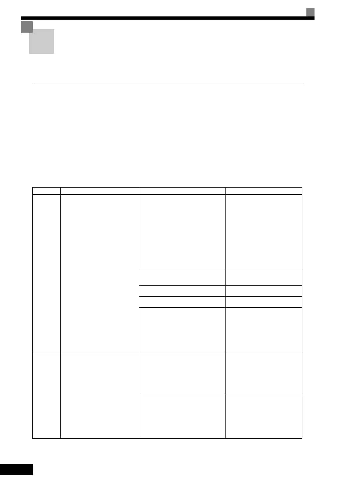
Table 7.1 Fault Displays and Processing
Display Meaning Probable Causes Corrective Actions
OC
Over Cur-
rent
Overcurrent
The Inverter output current
exceeded the overcurrent detection
level. (200% of rated current)
• A short-circuit or ground fault
occurred at the Inverter output. (A
short or ground fault can be caused
by motor burn damage, worn insula-
tion, or a damaged cable.)
• The load is too large or the accelera-
tion/deceleration time is too short.
• A special-purpose motor or motor
with a capacity too large for the
Inverter is being used.
• A magnetic contactor was switched
at the Inverter output.
Reset the fault after correcting its
cause.
Note: Before turning the power
ON again, make sure that no short-
circuit or ground fault occurs at the
Inverter output.
There is a break in the PG wiring.
Fix the broken/disconnected wir-
ing.
The PG is wired incorrectly. Fix the wiring.
Power isn't being supplied to the PG. Supply power to the PG properly.
• A short-circuit between +V, −V, and
AC terminals occurred.
• Overload in the control circuit termi-
nal.
• Make sure that incorrect wiring
has not been done.
• Check the resistance and wiring
for the frequency setting potenti-
ometer, etc. (Check that the cur-
rent for terminals +V and –V is
20 mA or less.)
GF
Ground
Fault
Ground Fault
*
The ground fault current at the
Inverter output exceeded approxi-
mately 50% of the Inverter rated
output current.
A ground fault occurred at the Inverter
output. (A ground fault can be caused
by motor burn damage, worn insulation,
or a damaged cable.)
Reset the fault after correcting its
cause.
Note: Before turning the power
ON again, make sure that no short-
circuit or ground fault occurs at the
Inverter output.
• A short-circuit between +V, −V, and
AC terminals occurred.
• Overload in the control circuit termi-
nal.
• Make sure that incorrect wiring
has not been done.
• Check the resistance and wiring
for the frequency setting potenti-
ometer, etc. (Check that the cur-
rent for terminals +V and –V is
20 mA or less.)
* The ground fault here is one which occurs in the motor wiring while the motor is running. A ground fault may not be detected in the following cases.
A ground fault with low resistance which occurs in motor cables or terminals.
A ground fault occurs when the power is turned ON.
TOE-S616-60.1.book 2 ページ 2017年8月4日 金曜日 午後3時41分
 Loading...


