8
-4
Periodic Maintenance of Parts
The Inverter is configured of many parts, and these parts must be operating properly in order to make full use
of the Inverter functions.
Among the electronic components, there are some that require maintenance depending on their usage condi-
tions. In order to keep the Inverter operating normally over a long period of time, it is necessary to perform
period inspections and replace parts according to their service life.
Periodic inspection standards vary depending the Inverter's installation environment and usage conditions.
The Inverter's maintenance periods are noted below. Keep them as reference.
Refer to Cooling Fan Replacement Outline (Page 8-8) for replacing a cooling fan and Circulation Fan
Replacement Outline (Page 8-18) for replacing a circulation fan.
To replace other parts, contact your Yaskawa representative or YASKAWA ELECTRIC ENGINEERING
CORPORATION for details on preventive maintenance for Inverters.
Note The standard replacement period is based on the following usage conditions:
Ambient temperature:Yearly average of 30°C
Load factor: 80% max.
Operating rate: 12 hours max. per day
Procedure for Adjusting Constants after Replacement of Control Board
Perform the following operations before adjusting the constants.
• For 400-V class Inverters of 55 kW to 300 kW with SPEC: E and later, take safety measures such as the
installation of an emergency-stop switch. Failure to do so may result in injury caused by the motor acci-
dentally rotating during stationary autotuning performed by the Inverter when the constants are adjusted.
• Before replacing the control board, first use the COPY function of the Digital Operator to copy the settings
of the constants of board from the Inverter to the Digital Operator.
When using the copy function of the Digital Operator, check that the following settings are the same between
the Inverter and the Digital Operator. Note the setting of A1-02 (Control method selection).
• Inverter product and type
• Software number
• Inverter capacity and voltage
• Control method
After replacing the board, use the following procedure to adjust the constants.
Steps 4 and 5 are not required for 400-V class Inverters of 0.4 kW to 45 kW, 400-V class Inverters of 55 kW to
300 kW with SPEC: A to C, and all models of 200-V class Inverters regardless of capacity. If using a 400-V
class Inverter of 55 kW to 300 kW with SPEC: E and later, use a control board, version ETC618046-S1033
and later, and then perform steps 4 and 5.
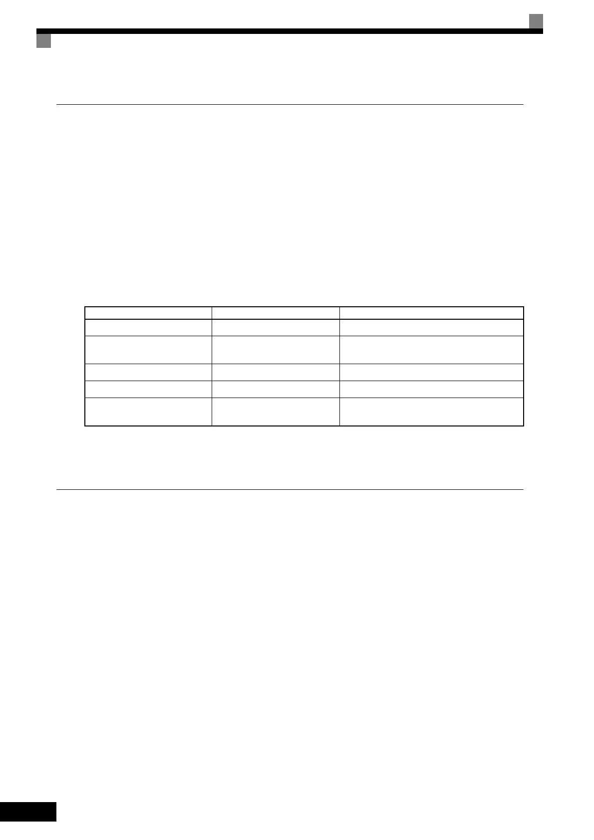
Table 8.2 Part Replacement Guidelines
Part Standard Replacement Period Replacement Method
Cooling fan 2 to 3 years Replace with new part.
Smoothing capacitor 5 years
Replace with new part.
(Determine need by inspection.)
Breaker relays – Determine need by inspection.
Fuses 10 years Replace with new part.
Aluminum capacitors on PCBs 5 years
Replace with new board.
(Determine need by inspection.)
TOE-S616-60.1.book 4 ページ 2017年8月4日 金曜日 午後3時41分
 Loading...


