Wiring Control Circuit Terminals
2-
31
Control Circuit Terminal Functions
The functions of the control circuit terminals are shown in Table 2.11. Use the appropriate terminals for the
correct purposes.
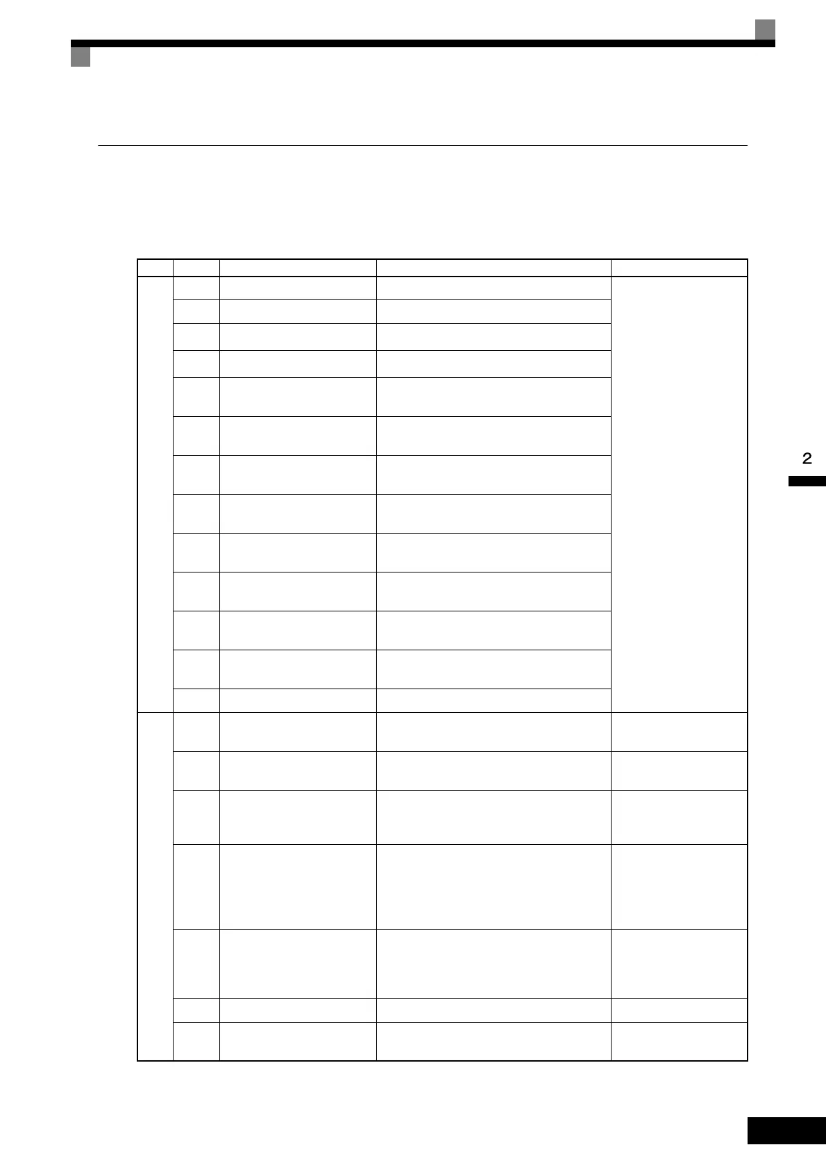
Table 2.11 Control Circuit Terminals
Type
No. Signal Name Function Signal Level
Se-
quence
input
signals
S1 Forward Run/Stop Command Forward run when ON; stopped when OFF.
24 VDC, 8 mA
Photocoupler isolation
S2 Reverse Run/Stop Command Reverse run when ON; stopped when OFF.
S3
Multi-function input 1
*1
Factory setting: External fault when ON.
S4
Multi-function input 2
*1
Factory setting: Fault reset when ON.
S5
Multi-function input 3
*1
Factory setting: Multi-step speed reference 1
effective when ON.
S6
Multi-function input 4
*1
Factory setting: Multi-step speed reference 2
effective when ON.
S7
Multi-function input 5
*1
Factory setting: Jog frequency selected when
ON.
S8
Multi-function input 6
*1
Factory setting: External baseblock when
ON.
S9
Multi-function input 7
*1
Factory setting: Multi-step speed reference 3
effective when ON.
S10
Multi-function input 8
*1
Factory setting: Multi-step speed reference 4
effective when ON.
S11
Multi-function input 9
*1
Factory setting: Acceleration/deceleration
time selected when ON.
S12
Multi-function input 10
*1
Factory setting: Emergency stop (NO con-
tact) when ON.
SC Sequence input common –
Analog
input
signals
+V +15 V power output +15 V power supply for analog references
+15 V
(Max. current: 20 mA)
-V -15 V power output -15 V power supply for analog references
-15 V
(Max. current: 20 mA)
A1
Master speed frequency ref-
erence
-10 to +10 V/-100 to 100%
0 to +10 V/100%
-10 to +10 V, 0 to +10 V
(Input impedance:
20 kΩ)
A2 Multi-function analog input
4 to 20 mA/100%, -10 to +10 V/-100 to
+100%, 0 to +10 V/100%
Factory setting: Added to terminal A1
(H3-09 = 0)
4 to 20 mA (Input imped-
ance: 250 Ω)
-10 to +10 V, 0 to +10 V
(Input impedance:
20 kΩ)
A3 Multi-function analog input
-10 to +10 V/-100 to +100%, 0 to +10 V/
100%
Factory setting: Auxiliary speed frequency
reference 1 (H3-05 = 2)
-10 to +10 V, 0 to +10 V
(Input impedance:
20 kΩ)
AC Analog reference common 0 V –
E(G)
Shield wire, optional ground
line connection point
––
TOE-S616-60.1.book 31 ページ 2017年8月4日 金曜日 午後3時41分
 Loading...


