2
-18
* 1. A star () indicates the recommended wire size for each capacity.
* 2. All Lug Kits are a three-piece set with a closed-loop crimp terminal and an insulation cap. A Lug Kit is required for both the input and the output.
When the Inverter is connected to 2P (or 4P), two Lug Kits (or four Lug Kits) are required for each phase.
Example 1: When using the CIMR-G7A2015 (when connecting 30 sq (AWG3) to both the input and output)
A total of 2 Kits, one 100-051-264 for the input and one for the output, are required.
Example 2: When using the CIMR-G7A4300 (when connecting 325 sq (600) × 2P to the input and 325 sq (600) × 2P to the output)
A total of four 100-051-278 Lug Kits are required because two Lug Kits are required for both the input and the output.
Main Circuit Terminal Functions
Main circuit terminal functions are summarized according to terminal symbols in Table 2.4. Wire the terminals
correctly for the desired purposes.
Table 2.4 Main Circuit Terminal Functions (200 V Class and 400 V Class)
Note The 1 and input terminals for the DC power do not conform to UL/cUL standards.
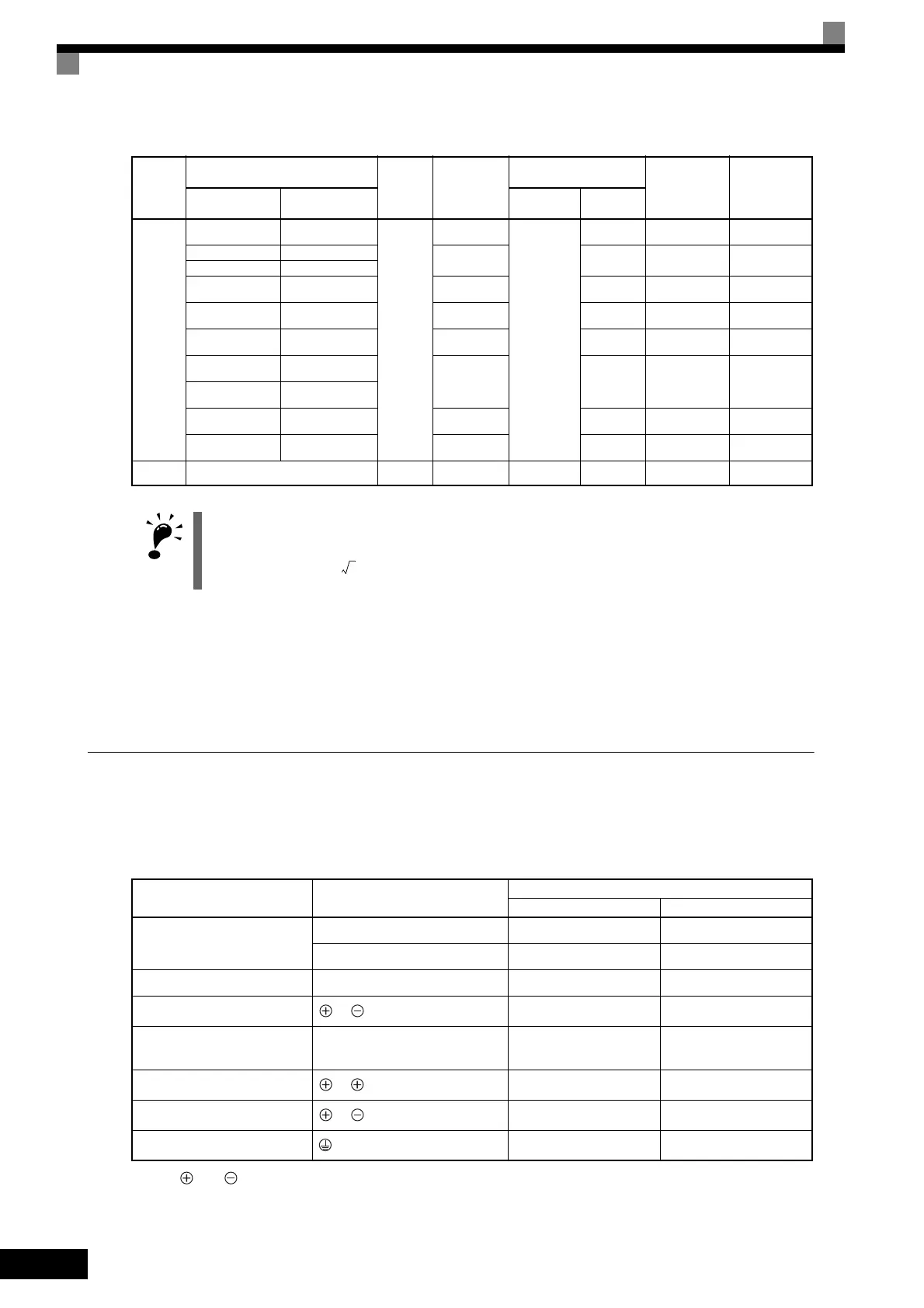
4300
100 (4/0) × 4P –
M16
RD100-14
YF-1
YET-300-1
TD-324,
TD-312
TP-100 100-051-271
125 (250) × 4P –
RD150-14
TD-325,
TD-313
TP-150 100-051-274
150 (300) × 4P –
200 (400) × 4P – RD200-14
TD-327,
TD-314
TP-200 100-051-276
325 (600) × 2P
*1
– RD325-14
TD-328,
TD-315
TP-325 100-051-278
– 100 (4/0) × 4P RD100-14
TD-324,
TD-312
TP-100 100-051-271
– 125 (250) × 4P
RD150-14
TD-325,
TD-313
TP-150 100-051-274
– 150 (300) × 4P
– 200 (400) × 4P RD200-14
TD-327,
TD-314
TP-200 100-051-276
–
325 (600) × 2P
*1
RD325-14
TD-328,
TD-315
TP-325 100-051-278
4300
(VT)
150 (300) × 4P
*1
M16 RD150-14
YF-1
YET-300-1
TD-325,
TD-313
TP-150 100-051-274
Determine the wire size for the main circuit so that line voltage drop is within 2% of the rated voltage. Line
voltage drop is calculated as follows:
Line voltage drop (V) =
x wire resistance (W/km) x wire length (m) x current (A) x 10
-3
Purpose Terminal Symbol
Model: CIMR-G7A
200 V Class 400 V Class
Main circuit power input
R/L1, S/L2, T/L3 20P4 to 2110 40P4 to 4300
R1/L11, S1/L21, T1/L31 2018 to 2110 4018 to 4300
Inverter outputs U/T1, V/T2, W/T3 20P4 to 2110 40P4 to 4300
DC power input
1,
20P4 to 2110 40P4 to 4300
Braking Resistor Unit connec-
tion
B1, B2 20P4 to 2015 40P4 to 4015
DC reactor connection
1, 2
20P4 to 2015 40P4 to 4015
Braking Unit connection
3,
2018 to 2110 4018 to 4300
Ground 20P4 to 2110 40P4 to 4300
Table 2.3 Closed-loop Crimp Terminal and Insulation Cap Sizes (200 V Class and 400 V Class) (Continued)
Inverter
Model
CIMR-
G7A
Wire Size sq (AWG)
Terminal
Screws
Closed-loop
Crimp
Terminals
Crimping Tool
Insulation Cap
Lug Kit Product
No.
*2
R/L1, S/L2, and
T/L3
U/T1, V/T2, and
W/T3
Tool Model Die
TOE-S616-60.1.book 18 ページ 2017年8月4日 金曜日 午後3時41分
 Loading...


