10
-26
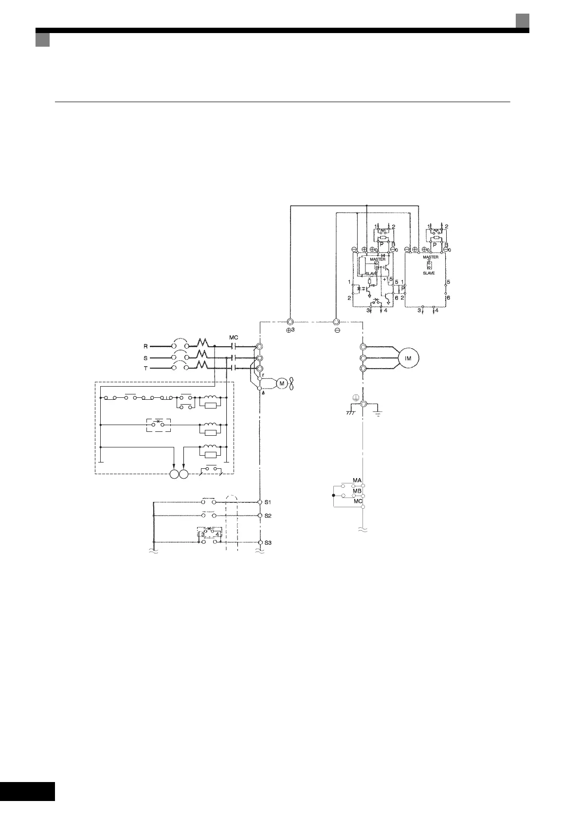
Using Braking Units in Parallel
This example shows wiring for using two Braking Units in parallel.
There are connectors for selecting whether each Braking Unit is to be a Master or Slave. Select “Master” for
the first Braking Unit only, and select “Slave” for all other Braking Units (i.e., from the second Unit onwards).
Fig 10.15
THRX
THRX
12
TRX
TRX
MBMC
2MCCB
MA MC
OFF
ON
MC
MC
SA
SA
SA
Braking Resistor Unit
thermal relay trip contacts
Fault contacts
A sequence is required to turn OFF the
power supply for the thermal overload relay
trip contacts of the Braking Resistor Unit.
Ground Fault Interrupter or Molded-case Circuit Breaker
Inverter
Motor
Ground to 100 Ω max.
Forward Run Com-
mand (forward run
when ON)
Reverse Run Com-
mand (reverse run
when ON)
Forward Run/Stop
Reverse Run/Stop
Braking Unit
External fault
3-phase power supply,
200 to 220 V at 50 Hz or
200 to 230 V at 60 Hz
Thermal
protector
Thermal
protector
Brak-
ing
Resis-
tor Unit
Braking
Resistor
Unit *
Thermal switch
Level
detector
Braking Unit 2
Thermal switch
Cooling fan
Fault contact output
* Disable the stall prevention during deceleration (set constant L3-04 to 0) when using a Brak-
ing Resistor Unit. If this user constant is not changed to disable stall prevention, the system
may not stop in the set deceleration time.
R/L1
S/L2
T/L3
U/T1
V/T2
W/T3
TOE-S616-60.1.book 26 ページ 2017年8月4日 金曜日 午後3時41分
 Loading...


