9
-4
Common Specifications
The following specifications apply to both 200 V and 400 V Class Inverters.
* 1. Rotational autotuning must be performed to ensure obtaining the specifications given for flux or open-loop vector 1/2 control.
* 2. When connecting a Braking Resistor or Braking Resistor Unit, set L3-04 (Stall prevention selection during deceleration) to 0 (disabled). Stopping may not be pos-
sible in the specified deceleration time if this function is not disabled.
* 3. The maximum output frequency for open-loop vector 2 control is 66 Hz (for PRG 103, 132 Hz).
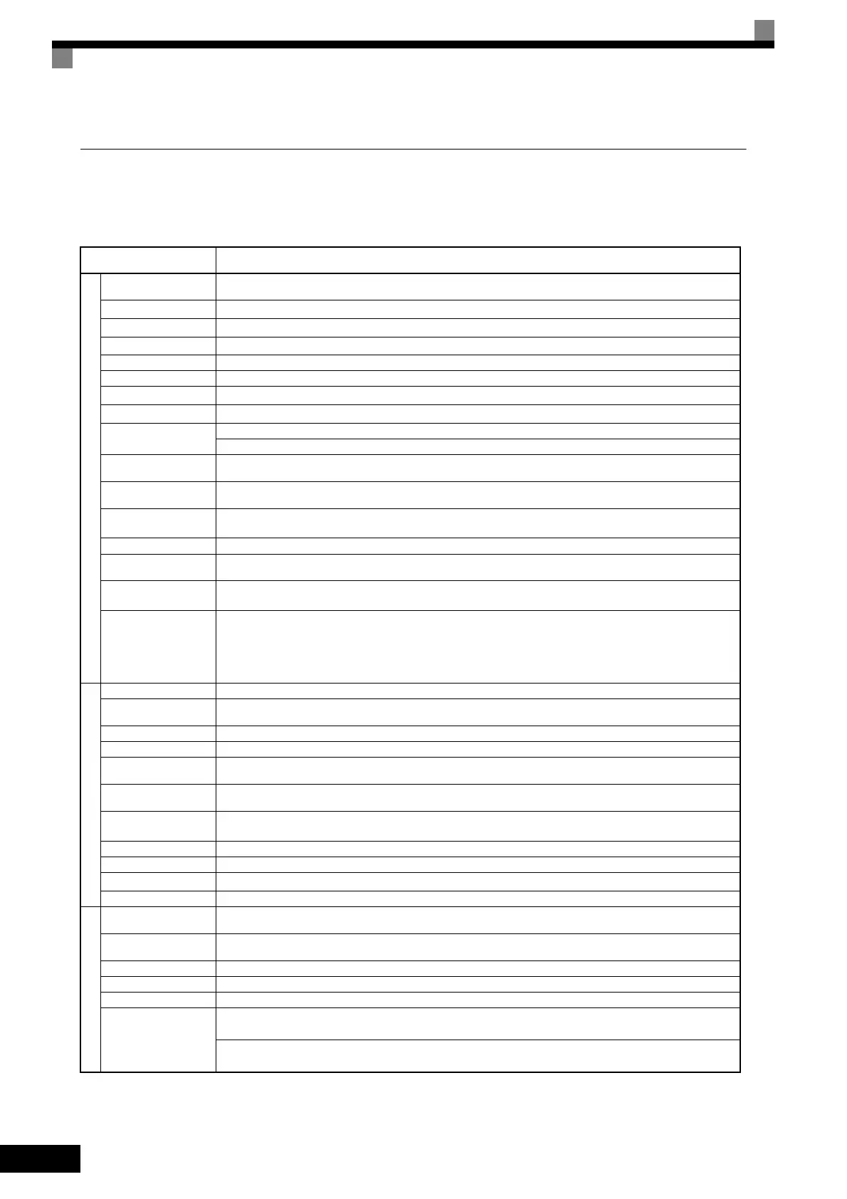
Table 9.3 Common Specifications
Model Number
CIMR-G7A
Specification
Control method
Sine wave PWM
Flux vector control, open-loop vector 1/2 control, V/f control, V/f with PG control (switched by constant setting)
Torque characteristics
150%/0.3 Hz (Open-loop vector 2 control), 150%/0 min
−1
(Flux vector control)
*1
Speed control range
1:200 (Open-loop vector 2 control), 1:1000 (Flux vector control)
*1
Speed control accuracy
*4
±0.2% (Open-loop vector 2 control, 25°C ± 10°C), ±0.02% (Flux vector control, 25°C ± 10°C)
Speed control response 10 Hz (Open-loop vector 2 control), 30 Hz (Flux vector control)
Torque limits Provided for vector control only (4 quadrant steps can be changed by constant settings.)
Torque accuracy
±5%
Frequency control range
0.01 to 400 Hz
*3 *9
Frequency accuracy (tem-
perature characteristics)
Digital references: ± 0.01% (-10°C to +40°C)
Analog references: ±0.1% (25°C ±10°C)
Frequency setting resolu-
tion
Digital references: 0.01 Hz, Analog references: 0.03 Hz/60 Hz (11 bit with no sign)
Output frequency resolu-
tion
0.001 Hz
Overload capacity and
maximum current
*2
150% of rated output current per minute
*5 *8
Frequency setting signal -10 to 10 V, 0 to 10 V, 4 to 20 mA, pulse train
Acceleration/Decelera-
tion time
0.01 to 6000.0 s (4 selectable combinations of independent acceleration and deceleration settings)
Braking torque
Approximately 20% (Approximately 125% with Braking Resistor option, braking transformer built into 200 V and 400 V Class
Inverters for 15 kW or less.)
*2
Main control functions
Restarting for momentary power loss, speed searches, overtorque detection, torque limits, 16-speed control (maximum), accelera-
tion/deceleration time changes, S-curve acceleration/deceleration, 3-wire sequence, autotuning (rotational or stationary), dwell
functions, cooling fan ON/OFF control, slip compensation, torque compensation, jump frequencies, upper and lower limits for
frequency references, DC braking for starting and stopping, high-slip braking, PID control (with sleep function), energy-saving
control, MEMOBUS communications (RS-485/422, 19.2 kbps maximum), fault reset, function copying, droop control (flux vec-
tor control only) torque control, speed/torque control switching, etc.
Motor protection Protection by electronic thermal overload relay.
Instantaneous overcurrent
protection
Stops at approx. 200% of rated output current.
Fuse blown protection Stops for fuse blown.
Overload protection 150% of rated output current per minute
Overvoltage protection
200 Class Inverter: Stops when main-circuit DC voltage is approximately above 410 V.
400 Class Inverter: Stops when main-circuit DC voltage is approximately above 820 V.
Undervoltage protection
200 Class Inverter: Stops when main-circuit DC voltage is approximately below 190 V.
400 Class Inverter: Stops when main-circuit DC voltage is approximately below 380 V.
Momentary power loss
ridethrough
*7
Stops for 15 ms or more.
With a suitable constant setting, operation can be continued if power is restored within 2 s.
Cooling fin overheating Protection by thermistor.
Stall prevention Stall prevention during acceleration, deceleration, or running.
Grounding protection
*6
Protection by electronic circuits. (Overcurrent level)
Charge indicator Lit when the main circuit DC voltage is approx. 50 V or more.
Ambient operating tem-
perature
-10°C to 40°C (Enclosed wall-mounted type)
10°C to 45°C (Open chassis type)
Ambient operating humid-
ity
95% max. (with no condensation)
Storage temperature - 20°C to + 60°C (short-term temperature during transportation)
Application site Indoor (no corrosive gas, dust, etc.)
Altitude 1000 m max.
Vibration
200 V Class, 0.4 to 37 kW, and 10 to 20 Hz: Permitted up to 9.8 m/s
2
400 V Class, 0.4 to 45 kW, and 20 to 55 Hz: Permitted up to 5.9 m/s
2
200 V Class, 45 to 110 kW, and 10 to 20 Hz: Permitted up to 9.8 m/s
2
400 V Class, 55 to 300 kW, and 20 to 55 Hz: Permitted up to 2.0 m/s
2
TOE-S616-60.1.book 4 ページ 2017年8月4日 金曜日 午後3時41分
 Loading...


