2
-42
Wiring
Wiring examples are provided in the following illustrations for the option boards.
Wiring the PG-A2
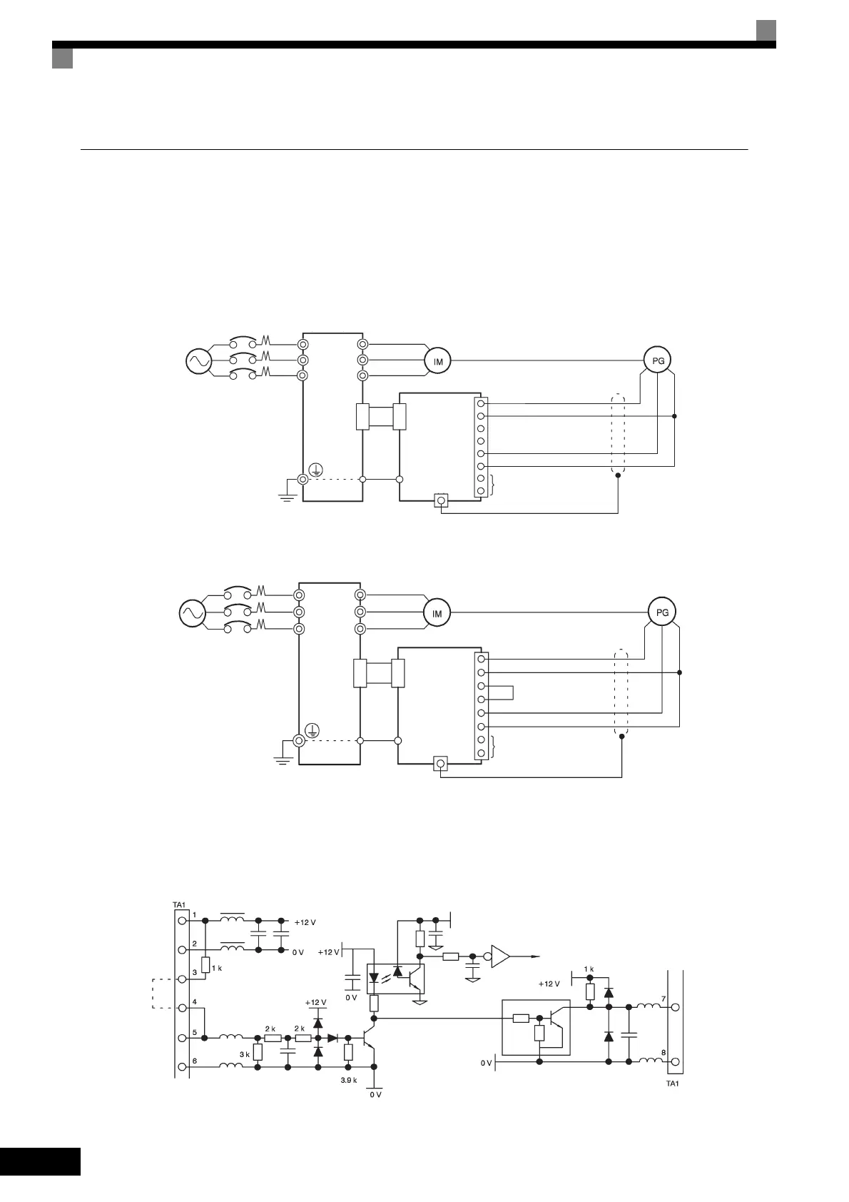
Wiring examples are provided in the following illustrations for the PG-A2.
Fig 2.23 Wiring a 12 V Voltage Input
•
Shielded twisted-pair wires must be used for signal lines.
• Do not use the pulse generator's power supply for anything other than the pulse generator (encoder).
Using it for another purpose can cause malfunctions due to noise.
• The length of the pulse generator's wiring must not be more than 100 meters.
Fig 2.24 Wiring an Open-collector Input
Fig 2.25 I/O Circuit Configuration of the PG-A2
Three-phase, 200
VAC (400 VAC)
Inverter
+12 V power supply
0 V power supply
12 V voltage input (A/B phase)
Pulse 0 V
Pulse monitor output
R/L1
S/L2
T/L3
U/T1
V/T2
W/T3
4CN
4CN
E
E
1
2
3
4
5
6
7
8
TA1
TA2 (E)
PC-A2
Three-phase,
200 VAC (400 VAC) Inverter
+12 V power supply
0 V power supply
Pulse input (+)
Pulse input (-)
Pulse monitor output
R/L1
S/L2
T/L3
U/T1
V/T2
W/T3
4CN
4CN
E
E
1
2
3
4
5
6
7
8
TA1
TA2 (E)
PG-A2
(Short circuit across
terminals 3-4)
PG power
supply
+12 V
Short for
open-col-
lector
input
Pulse
input
Pulse input
Pulse
monitor
output
TOE-S616-60.1.book 42 ページ 2017年8月4日 金曜日 午後3時41分
 Loading...


