8
-24
Removing and Mounting the Control Circuit Terminal Board
The control circuit terminal board can be removed and mounted without disconnecting the cables.
Removing the Control Circuit Terminal Board
1. Remove the Digital Operator and front cover.
2. Remove the connecting line connectors connected to FE and NC on the control circuit terminal board.
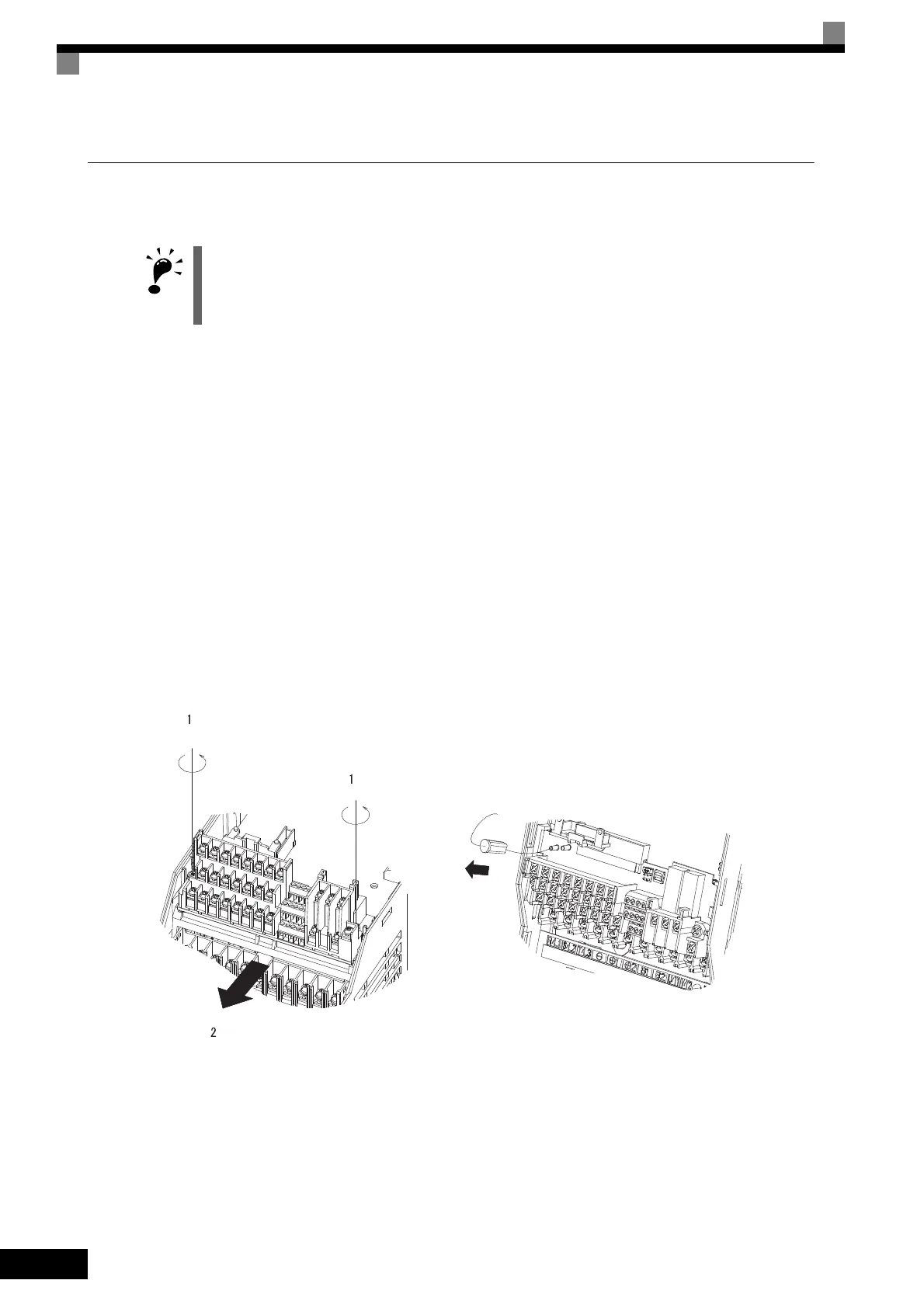
3. Loosen the mounting screws (1) on the left and right sides of the control terminals until they are free. (It is
not necessary to remove these screws completely. They are self-rising.)
4. Pull the terminal board out sideways (in direction 2) with the screws sticking out from the board.
Mounting the Control Circuit Terminal Board
Reverse the removal procedure to mount the terminal board.
Confirm that the control circuit terminal board and the control board properly meet at connector CN5 before
pressing in on the board.
The connector pins may be bent if the board is forced into place, possibly preventing correct Inverter opera-
tion.
Fig 8.18 Removing the Control Circuit Terminal Board
When removing or mounting the control circuit terminal board, turn OFF the input power supply and wait for 5
minutes or longer. Confirm that the CHARGE indicator has gone out.
Removing and Mounting the
Control Circuit Terminal Board
FE NC
TOE-S616-60.1.book 24 ページ 2017年8月4日 金曜日 午後3時41分
 Loading...


