6
-28
Adjusting Frequency References
This section explains methods of adjusting frequency references.
Adjusting Analog Frequency References
Gain and bias are among the constants used to adjust analog inputs.
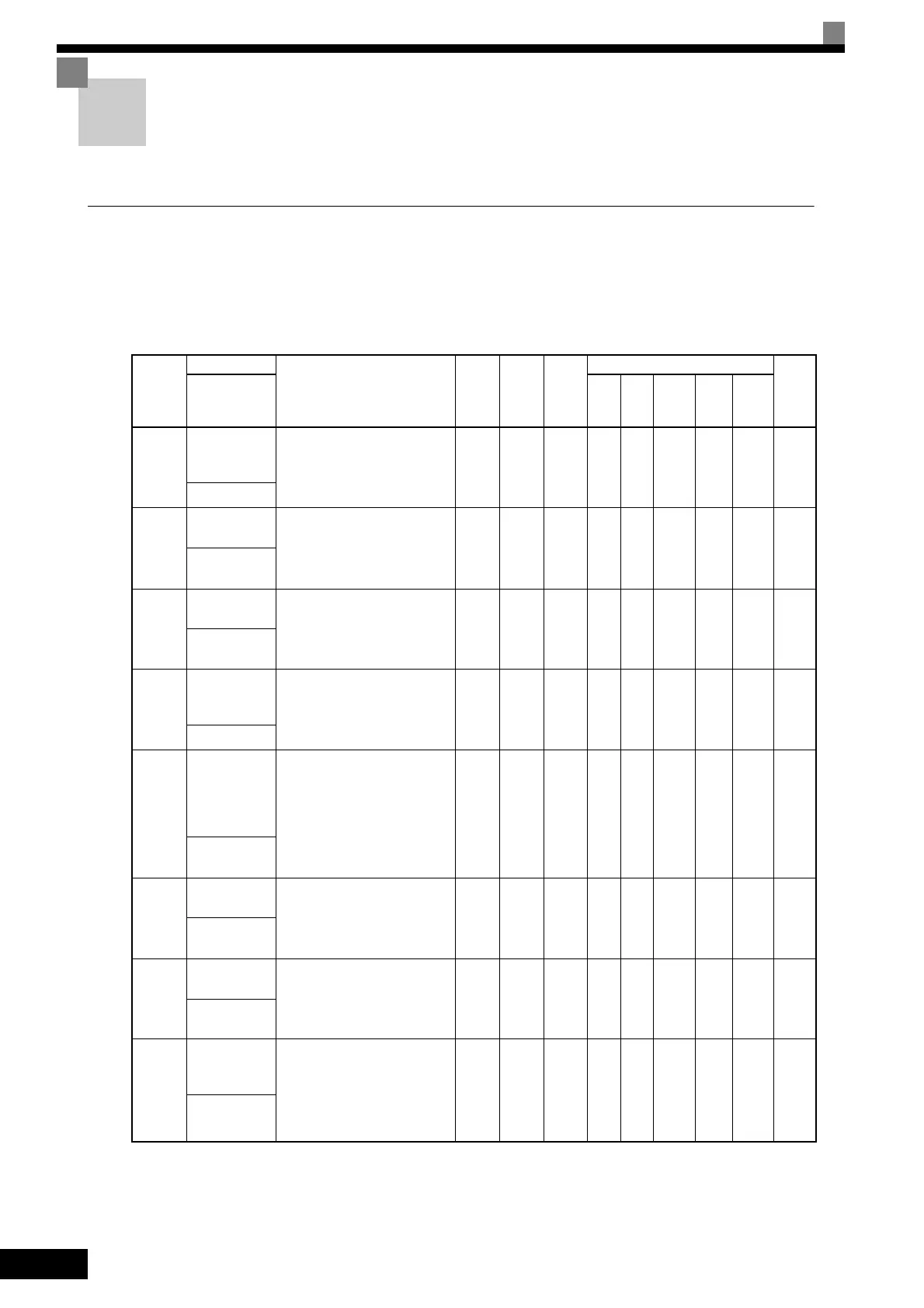
Related Constants
Con-
stant
Number
Name
Description
Setting
Range
Factory
Setting
Change
during
Opera-
tion
Control Methods
MEMO
BUS
Regis-
ter
Display
V/f
V/f
with
PG
Open
Loop
Vector
1
Flux
Vec-
tor
Open
Loop
Vector
2
H3-01
Signal level
selection (ter-
minal A1)
0: 0 to 10 V
1: -10 to 10 V
[11-bit + polarity (positive/
negative) input]
0 or 1 0 No A A A A A 410H
Term A1 Signal
H3-02
Gain (terminal
A1)
Sets the frequency when 10 V is
input, as a percentage of the maxi-
mum output frequency.
0.0 to
1000.0
100.0
%
Yes A A A A A 411H
Terminal A1
Gain
H3-03
Bias (terminal
A1)
Sets the frequency when 0 V is
input, as a percentage of the maxi-
mum frequency.
-100.0
to
+100.0
0.0% Yes A A A A A 412H
Terminal A1
Bias
H3-04
Signal level
selection (ter-
minal A3)
0: 0 to 10 V
1: -10 to 10 V
[11-bit + polarity (positive/
negative) input]
0 or 1 0 No A A A A A 413H
Term A3 Signal
H3-05
Multi-function
analog input
(terminal A3)
function selec-
tion
Select multi-function analog input
function for terminal A3.
0 to 1F 2 No A A A A A 414H
Terminal A3
Sel
H3-06
Gain (terminal
A3)
Sets the input gain (level) when
10 V is input.
Set according to the 100% value
selected from H3-05.
0.0 to
1000.0
100.0
%
Yes A A A A A 415H
Terminal A3
Gain
H3-07
Bias (terminal
A3)
Sets the input gain (level) when
0 V is input.
Set according to the 100% value
selected from H3-05.
-100.0
to
+100.0
0.0% Yes A A A A A 416H
Terminal A3
Bias
H3-08
Signal level
selection
(terminal A2)
0: 0 to 10 V
1: -10 to 10 V
2: 4 to 20 mA (9-bit input).
Switch current and voltage input
using the switch on the control
panel.
0 to 2 2 No A A A A A 417H
Term A2 Signal
TOE-S616-60.1.book 28 ページ 2017年8月4日 金曜日 午後3時41分
 Loading...


