2
-36
Control Circuit Wiring Precautions
Observe the following precautions when wiring control circuits.
• Separate control circuit wiring from main circuit wiring (terminals R/L1, S/L2, T/L3, B1, B2, U/T1, V/T2,
W/T3, , 1, 2, and 3) and other high-power lines.
• Separate wiring for control circuit terminals MA, MB, MC, M1, and M2 (contact outputs) from wiring to
other control circuit terminals.
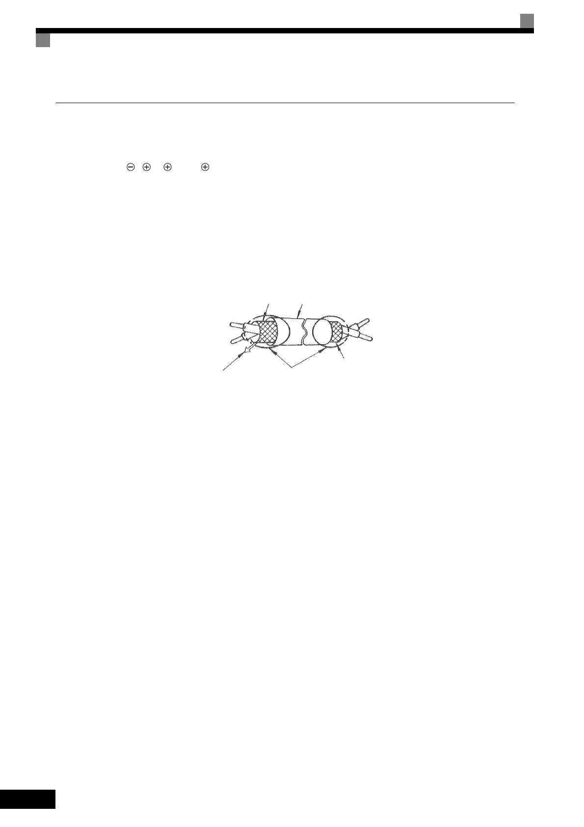
• Use shielded twisted-pair cables for control circuits to prevent operating faults. Process cable ends as
shown in Fig 2.20.
• Connect the shield wire to terminal E (G).
• Insulate the shield with tape to prevent contact with other signal lines and equipment.
• Use a class 2 power supply (UL standard) when connecting to the control terminals.
Fig 2.20 Processing the Ends of Shielded Twisted-pair Cables
Shield sheath
Armor
Connect to shield sheath
terminal at Inverter
(terminal E (G)).
Insulate with tape
Do not connect here.
TOE-S616-60.1.book 36 ページ 2017年8月4日 金曜日 午後3時41分
 Loading...


