6-84 Removal and Replacement
Magnetic Stripe Option
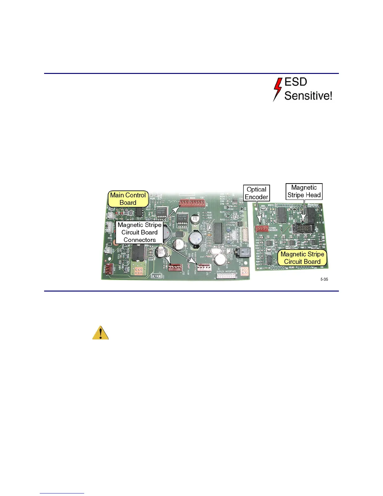
Magnetic Stripe Circuit Board
Removal Procedure
1. Turn off the printer and unplug the power cord.
2. Remove the ribbon cartridge and cleaning roller.
3. Remove the
Main Enclosure (page 6-15).
4. Remove the
Upper Printer Assembly from the base (page 6-38).
5. Unplug the magnetic stripe head and encoder cables from the magnetic stripe
board.
6. Remove the magnetic stripe circuit board from the main control board by
lifting the board off all three connectors simultaneously.
Replacement Notes
• There is no built-in alignment mechanism between the main control board
and the daughter board.
Caution. Make sure the connectors between the two boards are aligned
properly. If not, both boards could be damaged.
• Using the Diagnostics in chapter 5, calibrate the magnetic stripe head as
described in Start Sentinel Position.
 Loading...