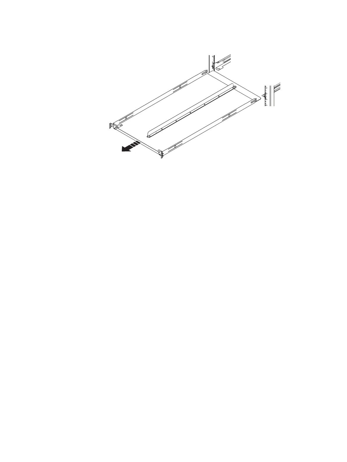
Figure 58 Remove the tray
9. At the front of the tray, push up on the spring clips and pull the tray towards
the front of the rack until it is free from the rails.
10. Remove the knurled screws from the front and back of the rails.
11. Pull back on the rails until the adaptors clear the front of the rack holes.
Remove the rails.
Non-EMC rack installation
Follow these best practice guidelines to ensure a more orderly installation:
l
Non-EMC racks may have PDUs which face into the rack. This may cause
interference between the shelf and/or rear CMAs (if used). Carefully plan and
route cables to minimize any interference. It may be necessary to use a different
type of PDU that is mounted in the main rack area.
l
The shelf rails have four adjustment ranges, 18-22", 22-26", 26-30", 30-34". The
default length (out of the shipping crate) is the 22-26" setting.
l
After installation, check each rail to ensure that it is level and in the correct
location before installing the next rail.
l
When securing rails to the NEMA channel, especially channels with square holes,
install the screws loosely to prevent cross threading, and tighten by hand. Do not
over torque.
l
Use black M5 screws, which align with both round and square channel holes, to
secure all rails and components in the customer racks. Discard all silver screws
removed from the shipping rack.
Shelf rail installation in non-EMC racks
Shelf rails require 4Us of contiguous space. The same kit, PN 106-569-209, is used for
all drive configurations.
Shelf Installation and Removal
62 EMC Data Domain DS60 Expansion Shelf Installation and FRU Replacement Hardware Guide
 Loading...