SC-F9200 Series Revision B
DISASSEMBLY & ASSEMBLY Disassembly and Assembly Procedure 123
SE Group Confidential (Related Staff Only)
3.4.4 Electric Circuit Components
3.4.4.1 Main Board
1. Remove the Board Box Cover. (p117)
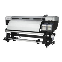
2. Disconnect the cables from the connectors (CN5, CN15) on the Main Board.
3. Remove the four screws, and remove the Main-B Board together with the
mounting plate.
A) Silver M3x6 screw: 4 pcs
Figure 3-46. Removing the Mounting Plate
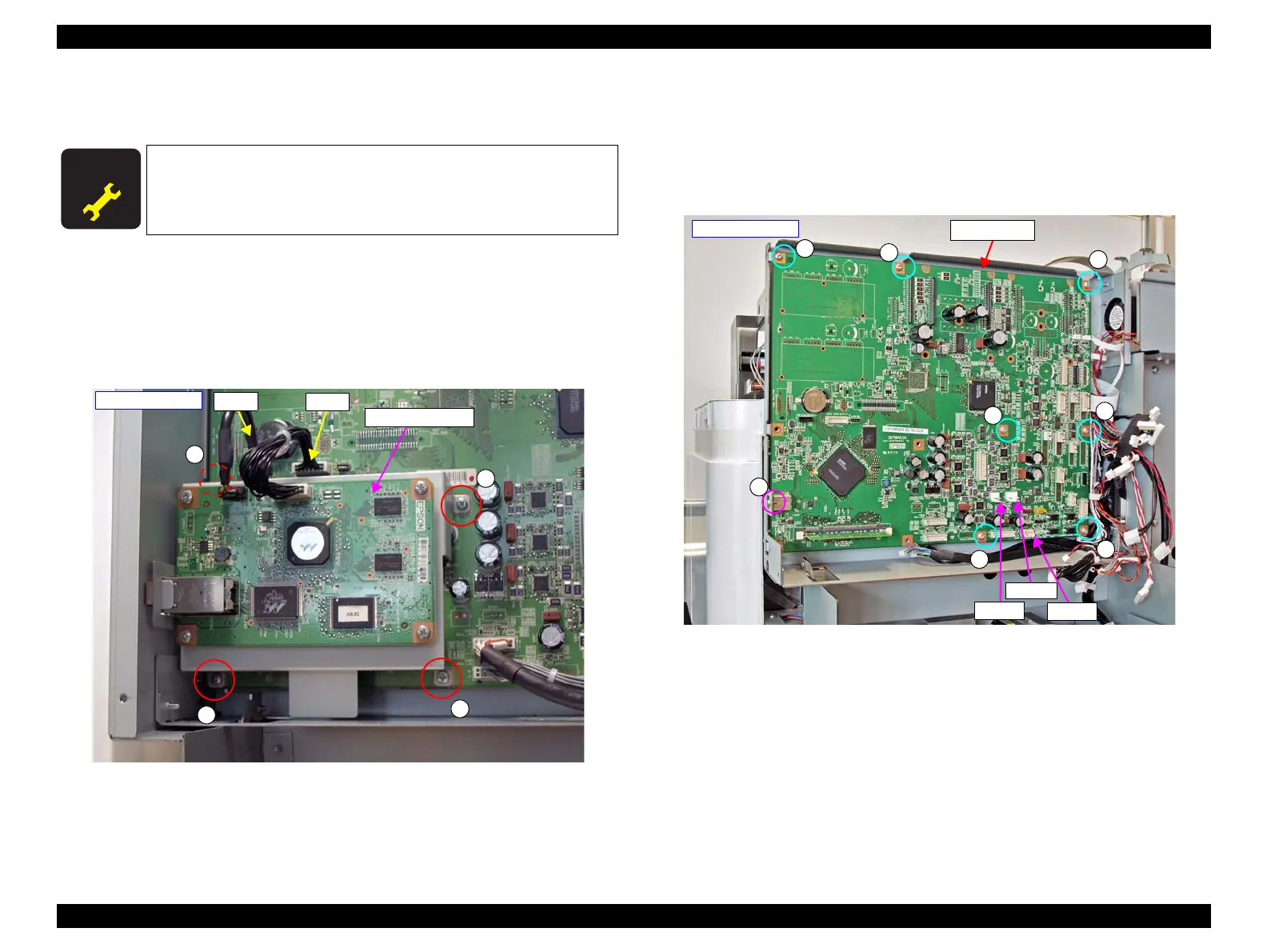
4. Disconnect all cables and FFCs from the Main Board.
5. Remove the eight screws, and remove the Main Board.
B) Silver M3x6 screw: 7 pcs
C) Silver M3x6 screw (USB fixing screw): 1 pcs
Figure 3-47. Removing the Main Board
A D J U S T M E N T
R E Q U I R E D
When replacing/removing this part, refer to “4.1.2 Adjustment
Items and the Order by Repaired Part” (p260) and make sure to
perform the specified operations including required adjustment.
A
A
A
A
- Right rear side -
Main-B Board
CN5
CN15
B
B
B
B
B
B
B
C
CN202
CN204
CN270
Main Board
- Right rear side -
 Loading...