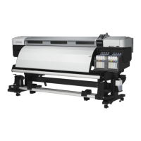
SC-F9200 Series Revision B
DISASSEMBLY & ASSEMBLY Disassembly and Assembly Procedure 140
SE Group Confidential (Related Staff Only)
3.4.5.2 Duct CR
REQUIRED TOOL
Ink Cartridge for service (4 pcs)
USB cable
Service program
Communication driver
PREPARATION BEFORE REPLACEMENT
1. Start the printer in the Serviceman Mode.
Turn on the printer while pressing [Menu] + [Back] + [OK].
2. Start the service program and select When replace Duct CR from
ADJUSTMENT (Sequence).
3. Select Duct CR Counter.
Press the [Run] button to reset the counter.
(p293)
4. Turn off the printer.
5. Start the printer in the Serviceman Mode.
Turn on the printer while pressing [Menu] + [Back] + [OK].
6. Select Tube inner pressure reduction.
Press the [Run] button to reduce the pressure in the tube.
(p308)
7. Select Switch between Ink cartridges and Ink tanks.
Select All channels and Ink Cartridge for service, and press the [Run] button to
validate the ink cartridges for service. (p329)
8. Select Auto CR unlock & move CR to full column side.
Press the [Run] button.
The CR lock is released and the CR Unit moves to the full side, then the printer
turns off automatically.
REPLACEMENT
1. Remove the Left Rear Cover.
(p110)
2. Remove the Left Upper Cover. (p111)
3. Remove the CR Cover. (p139)
4. Remove the clamp.
5. Remove the two screws that secure the Ink Path Holder Assy.
A) Silver M3x10 screw with washer: 2 pcs
6. Disengage the FFC from the hooks and hold up the Ink Path Holder Assy.
A D J U S T M E N T
R E Q U I R E D
When replacing/removing this part, refer to “4.1.2 Adjustment
Items and the Order by Repaired Part” (p260) and make sure to
perform the specified operations including required adjustment.
When the Ink Path Joint is removed at the following step, ink may
drip off from the tube. Prepare a waste cloth or the like in advance
and be careful not to contaminate the surroundings.
Pulling the Ink Path Holder Assy toward the rear as much as
possible, disconnect the FFC. Be careful not to damage the FFC.
 Loading...