13.10 Calculation Formula
198
Note) c: measured channel, M: number of samples per period, s: number of sampling points
Note) c: measured channel, M: number of samples per period, s: number of sampling points
13.10 Calculation Formula
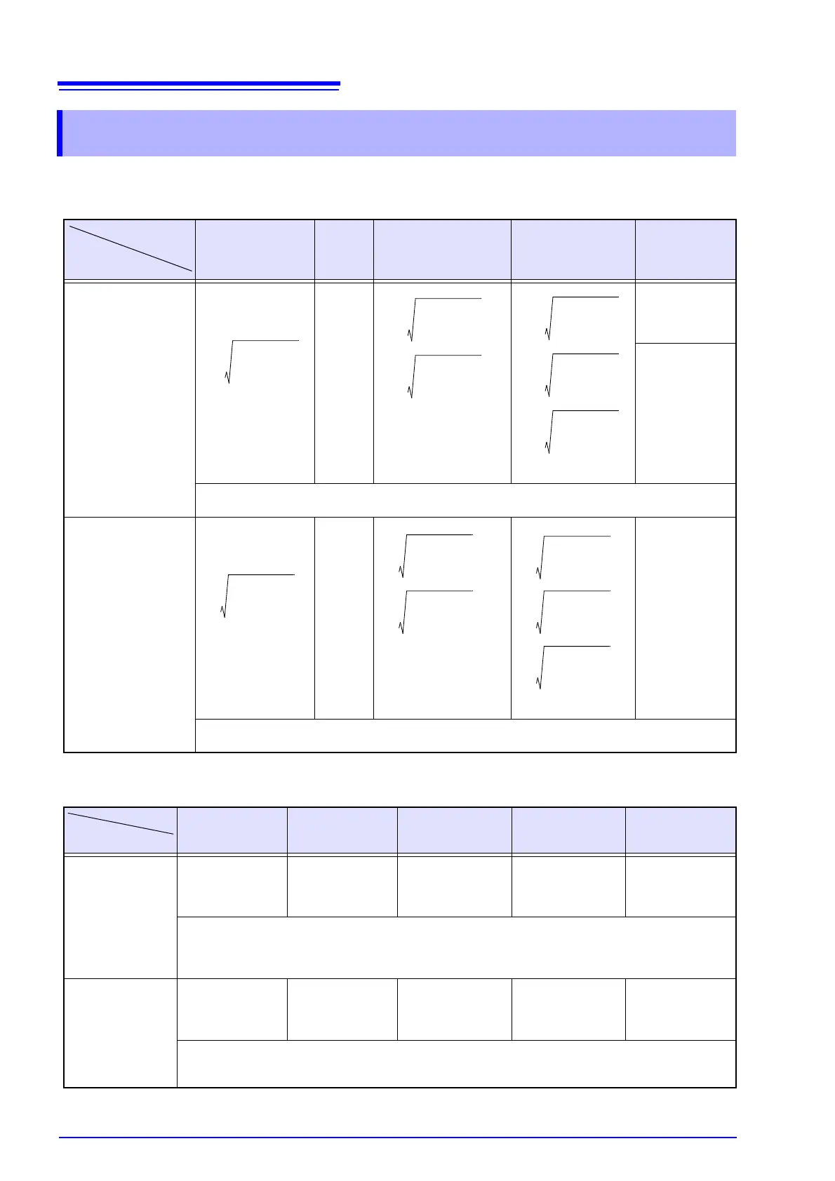
RMS voltage refreshed each half-cycle (Urms1/2), Dip (Dip), Swell (Swell), interrup-
tion (Intrpt), RMS current refreshed each half-cycle (Irms1/2), inrush current (Irms1/2)
Single-phase 2-wire
1P2W
Single-
phase 3-
wire
1P3W
Three-phase 3-wire
3P3W2M
Three-phase 3-wire
3P3W3M
Three-phase
4-wire
3P4W
Urms1/2
Dip
Swell
Intrpt
U
1
U
4
Uc=
U
1
U
2
U
4
Line-to-line voltage
U
12
=
U
32
=
U
31
is calculated from the
RMS value for (U3s=U2s-
U1s).
U
4
Line-to-line voltage
U
12
=
U
23
=
U
31
=
U
4
U
1
U
2
U
3
U
4
With 3P4W2.5E
connections
U2(U2s=-U1s-U3s)
(Assumes U1s +
U2s + U3s = 0.)
• For 50/60 Hz measurement, calculated with 1 overlapping waveform each half-cycle.
• For 400 Hz measurement, calculated with 1 waveform (M = number of samples in one 400 Hz period).
Irms1/2 (Inrush current) I
1
I
4
Ic=
I
1
I
2
I
4
Line-to-line voltage
I
1
=
I
2
=
I
3
is calculated from the
RMS value for (I3s=-I1s-
I2s).
I
4
Line-to-line voltage
I
1
=
I
2
=
I
3
=
I
4
I
1
I
2
I
3
I
4
• For 50/60 Hz measurement, calculated each half-cycle.
• For 400 Hz measurement, calculated with 1 waveform.
Voltage Waveform Peak (Upk), Current Waveform Peak (Ipk)
Single Phase 2-wire
1P2W
Single Phase 3-wire
1P3W
3-Phase, 3-Wire,
2-Measurement
3P3W2M
3-Phase, 3-Wire,
3-Measurement
3P3W3M
3-Phase, 4-Wire
3P4W
Upk+
Upk-
U
p1
U
p4
U
p1
U
p2
U
p4
U
p12
U
p23
U
p4
U
p12
U
p23
U
p31
U
p4
U
p1
U
p2
U
p3
U
p
• The maximum positive and negative values are calculated for all points with 10 waveforms (50 Hz measure-
ment) or 12 waveforms (60 Hz measurement). For 400 Hz measurement, the calculation is performed with 80
waveforms.
• The CH4 voltage peak value can be calculated regardless of the connection type.
Ipk+
Ipk-
I
p1
I
p4
I
p1
I
p2
I
p4
I
p1
I
p2
I
p4
I
p1
I
p2
I
p3
I
p4
I
p1
I
p2
I
p3
I
p4
• The maximum positive and negative values are calculated for all points with 10 waveforms (50 Hz) or 12
waveforms (60 Hz). During 400 Hz measurement, the calculation is performed with 80 waveforms.
• The voltage waveform peak for CH4 can be calculated regardless of the connection method.
 Loading...