3.6 Connecting the Voltage Cords
34
Be sure to read the "Usage Notes" (p.6) before connecting voltage cords.
Plug the voltage cord leads into the voltage input jacks on the instrument (the number of connec-
tions depends on the lines to be measured and selected wiring mode).
Be sure to read the "Usage Notes" (p.6) before connecting clamp sensors.
Plug the Clamp sensor cables into the current measurement jacks on the instrument (the number of con-
nections depends on the lines to be measured and selected wiring mode). See the instruction manual
supplied with the Clamp sensor for specification details and usage procedures.
3.6 Connecting the Voltage Cords
To prevent an electric shock accident, confirm that the white or red portion (insulation
layer) inside the cable is not exposed. If a color inside the cable is exposed, do not use
the cable.
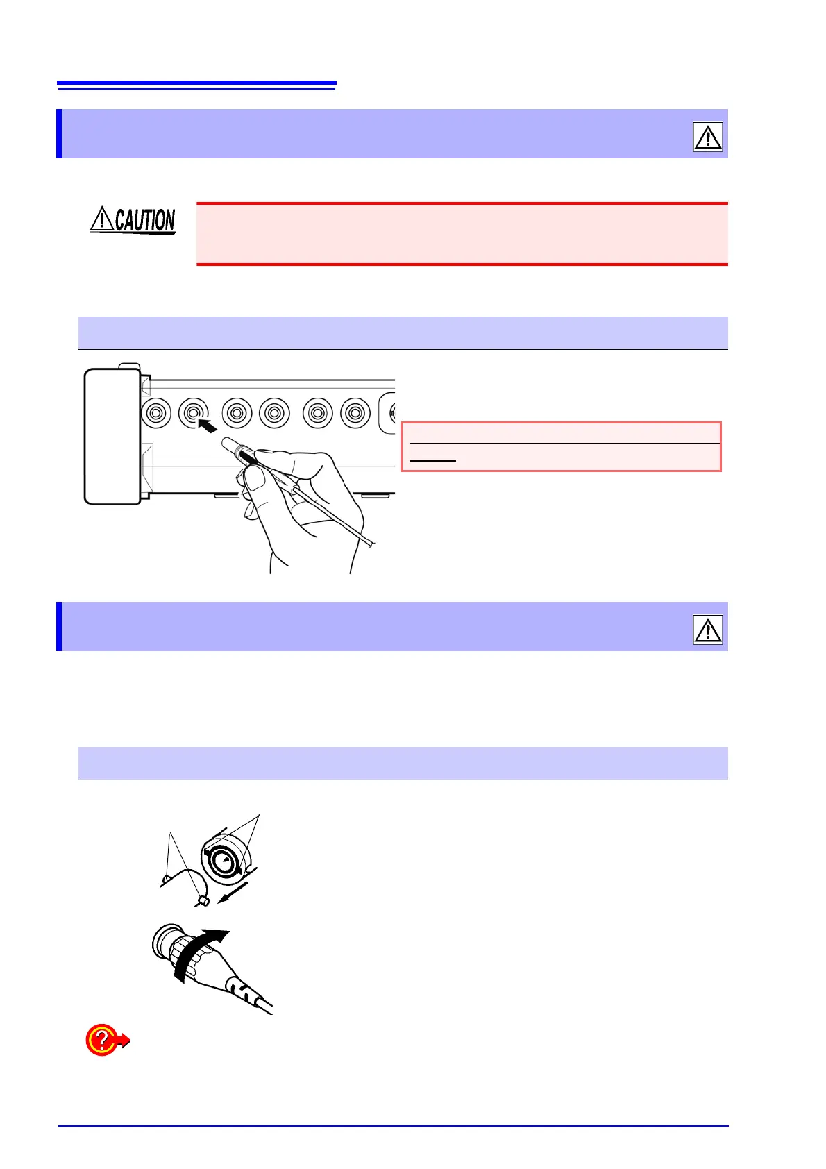
Connection Procedure
Plug the voltage cables into the appropri-
ate channels' voltage measurement jacks.
Insert the plugs into the jacks as far as they
will go.
3.7 Connecting the Clamp Sensors
Connection Procedure
Lock
BNC
connector
PW3198 current input jack
Connector, aligning
1. Insert the clamp sensor's BNC connector,
aligning its groove with the connector
guide on the instrument’s current input
jack.
2. Turn the connector clockwise to lock it in
place.
(To disconnect the connector, turn it counterclock-
wise to unlock it and then pull.)
1
2
To measure voltage and current beyond the range of the instrument or clamp sensor
Use an external VT (PT) or CT. By specifying the VT or CT winding ratio on the instrument,
the input level at the primary side can be read directly.
See: "4.7 Quick setup" (p.50)
 Loading...